Description
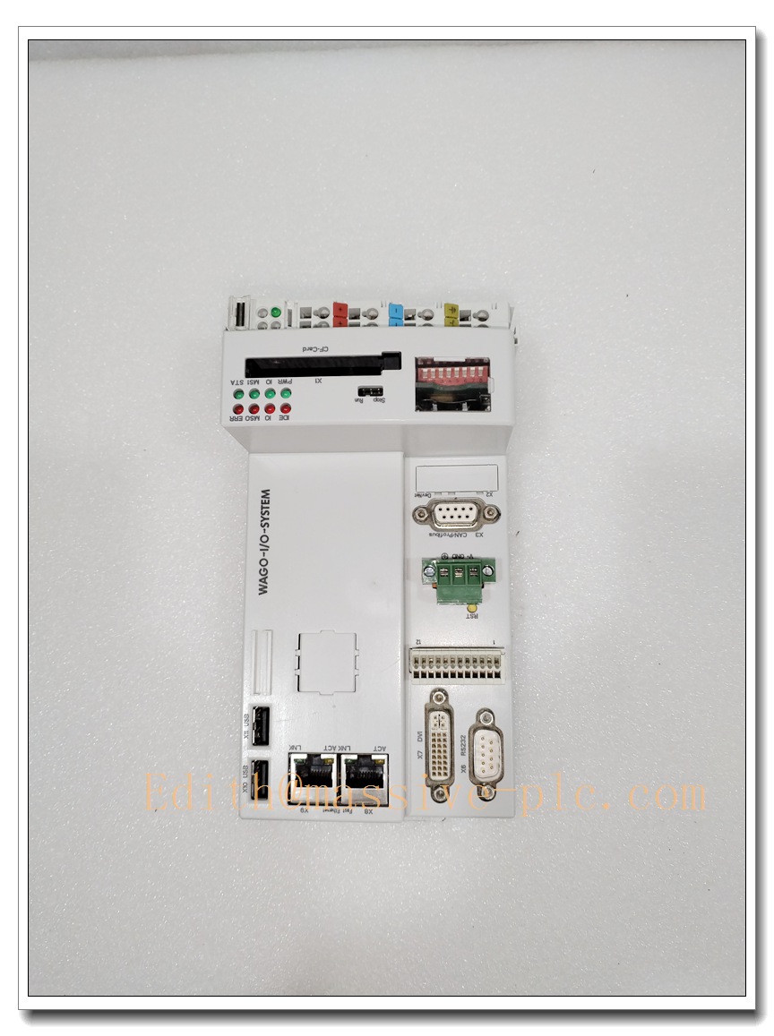
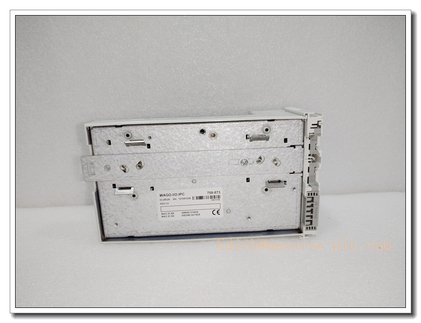
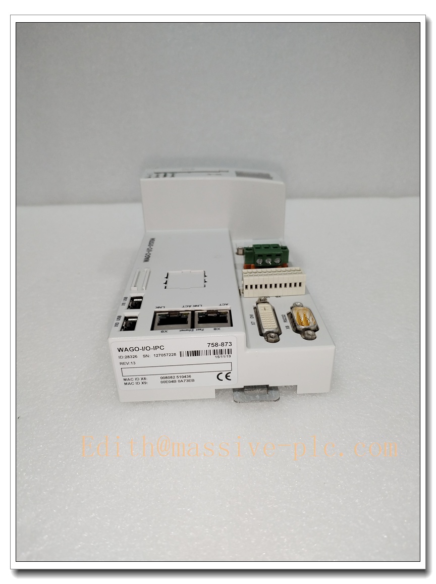
WAGO 758-873 | WAGO-I/O-IPC PFC200 Programmable Field Controller for WAGO-I/O-SYSTEM 750
Product Description
The WAGO 758-873 is a high-performance industrial embedded controller (IPC / PLC) within the WAGO PFC200 family, built for the modular WAGO-I/O-SYSTEM 750 fieldbus I/O rack. Powered by a 32-bit ARM Cortex‑M4 processor, it runs CODESYS V3, fully compliant with IEC 61131‑3 standard for industrial control programming. It can directly drive 750 series digital/analog I/O modules to realize real-time logic control, data acquisition and communication tasks. It features dual independent Ethernet ports for network redundancy, 1×RS232/RS485 serial interface, microSD card slot for program/data storage, and dual redundant 24VDC power input. It adopts WAGO patented CAGE CLAMP® spring-cage terminal connection technology, vibration-resistant and maintenance-free. Widely used in marine automation, power, energy, process control and factory automation for high-availability control systems.
Technical Specifications
| Item | Parameter |
|---|---|
| Brand | WAGO (万可) |
| Model | 758-873, WAGO-I/O-IPC PFC200 |
| CPU | 32-bit ARM Cortex-M4 |
| Runtime | CODESYS V3, IEC 61131-3 |
| Memory | 512MB program memory, 2MB retain data memory |
| Communication | 2 × Fast Ethernet 10/100 Mbps; 1 × RS232/RS485 |
| Storage | microSD card slot (for program, log, data backup) |
| Power Supply | 24 VDC (18…30 VDC), dual redundant power input |
| Power Consumption | Max approx. 270mA @24VDC |
| I/O Backplane | WAGO 750 series fieldbus I/O bus, expandable with 750 I/O modules |
| Mounting | Standard 35mm DIN rail |
| Operating Temperature | -25°C ~ +60°C |
| Storage Temperature | -40°C ~ +85°C |
| Humidity | 5%~95% non-condensing |
| Connection | CAGE CLAMP® spring terminals |
| Enclosure Rating | IP20 (cabinet installation) |
| Certification | CE, marine / DNV approvals available, IEC61131-3 |
| Weight | Approx. 320 g |
Compatibility & Installation Pitfalls
Compatibility
- I/O System: WAGO-I/O-SYSTEM 750 series I/O modules (DI, DO, AI, AO, RTD, TC etc.)
- Programming Tool: CODESYS V3 for WAGO PFC200
- Fieldbus: Modbus TCP, Modbus RTU, EtherNet/IP, PROFINET (by firmware)
- Not compatible: Older CODESYS V2 WAGO controllers (750-8xx non-PFC200), non-WAGO I/O racks
Critical Installation Pitfalls
- Redundant power wiring: Dual 24VDC power inputs should come from separate power sources to realize true power redundancy. Do not connect both channels to one single power supply.
- CODESYS firmware matching: Controller firmware must match CODESYS runtime version. Mismatched firmware leads to download failure or runtime crash.
- Backplane I/O bus limit: Total number of 750 I/O modules must not exceed the maximum station capacity. Too many modules cause bus communication timeout.
- SD card usage: Use industrial-grade microSD. Commercial SD cards may corrupt program files under vibration / temperature cycling. SD card is required for program backup and data logging.
- Shield & grounding: Ethernet / RS485 communication cables use shielded twisted pair, single-point grounding. Multiple earth points create ground loop noise.
- DIN rail installation: Lock the module firmly on DIN rail. In high vibration environments (marine, turbine cabinets), loose mounting causes intermittent backplane contact.
- No hot-swap for controller: 758-873 main controller cannot be hot swapped while the rack is running. Stop the control application and cut power before removal.
Standard Operating Procedure (SOP)
- Pre-Install Inspection & LOTO Lock-out tag-out 24VDC power. Inspect controller housing, terminals and backplane connector for damage. Confirm part number 758-873, check hardware revision. Prepare CODESYS V3 project.
- DIN Rail Mounting Clip 758-873 onto 35mm DIN rail, confirm locking latch fully engaged. Assemble 750 I/O modules sequentially on the right side of the controller.
- Power & Communication Wiring Wire dual redundant 24VDC power to controller power terminals. Connect Ethernet and RS485 field communication cables, use shielded twisted pair. Complete continuity test.
- CODESYS Project Download Open CODESYS V3, configure hardware tree with 758-873 and all 750 I/O modules. Compile control logic, set IP address and communication parameters, download application to controller.
- Power-Up & Commissioning Apply 24VDC power. Wait for controller boot and runtime start. Verify I/O channel read/write, network connection, Modbus / Ethernet communication. Test control logic and failover function.
- Runtime Operation & Diagnostics Monitor controller status, memory, network and I/O health via CODESYS visualization or web server. Regularly back up project to microSD card.
- Replacement Procedure Stop control application and execute LOTO. Disconnect power and communication cables. Remove old controller from DIN rail. Install spare 758-873, rewire, download project, verify all control and communication functions.
Application Scenarios
- Marine automation & vessel dynamic positioning systems
- Power plant auxiliary control & renewable energy automation
- Oil & gas skid control and process monitoring
- Factory machine control & material handling
- Building energy management & HVAC control
- Retrofit & spare parts replacement for existing WAGO 750 I/O systems
Supporting Components
- 35mm standard DIN rail
- WAGO 750 series I/O modules (DI/DO/AI/AO/RTD/TC)
- Industrial microSD card
- CODESYS V3 programming software
- Redundant 24VDC power supply
- Shielded Ethernet & RS485 twisted pair cables
- CAGE CLAMP wiring tools
- Circuit breakers for power protection
- Web visualization HMI or SCADA system
- WAGO end terminal modules for I/O station termination
Related Model Recommendations (10 Models)
- 758-870: PFC200 controller variant
- 758-874: PFC200 controller
- 758-875: PFC200 controller
- 758-876: PFC200 controller
- 750-461: Analog input module 4-20mA
- 750-550: Analog output module
- 750-430: Digital input module
- 750-530: Digital output module
- 750-455: RTD temperature input module
- 750-600: End module for 750 I/O station