
Description
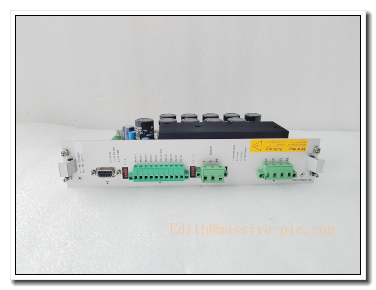
Berger Lahr BLS2020 C162 BLS2020 Series Stepper Drive Control Board
Product Core Introduction
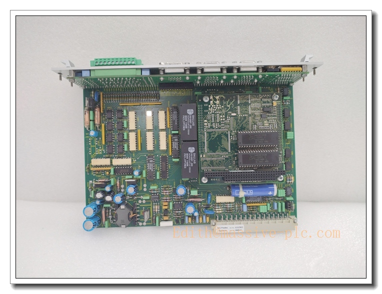
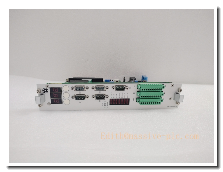
The BLS2020 C162 is a rack-mounted stepper drive control board from Berger Lahr (now part of Schneider Electric). It is the main control card for BLS2020 series stepper drive systems, responsible for motion profile generation, micro-stepping control, pulse/direction command processing, fault monitoring and host communication. It drives Berger Lahr 5-phase stepper motors, widely used in printing, packaging, textile and machine tool automation for precise positioning. This product is OEM discontinued; available stock is fully tested refurbished & surplus spare units for legacy machine maintenance.
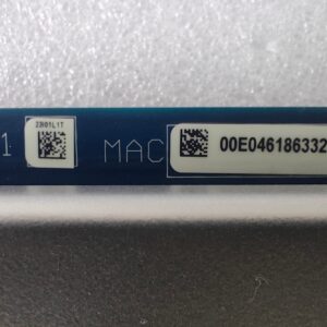
BLS2020 C162
Main Technical Specifications
| Technical Parameter | Specification Value |
|---|---|
| Model | BLS2020 C162 (Berger Lahr) |
| Product Type | Stepper motion control board (BLS2020 rack card) |
| Motor Type | 5-phase stepper motor |
| Control Mode | Micro-stepping, pulse/direction, bus command |
| Command Interface | Pulse & direction / serial communication |
| Diagnostic | LED status indication, fault code output |
| Power Supply | Powered by rack backplane |
| Operating Temperature | 0 ℃ ~ +50 ℃ (cabinet ambient) |
| Storage Temperature | -40 ℃ ~ +85 ℃ |
| Operating Humidity | 5% ~ 85% RH, non-condensing |
| Mounting | Rack plug-in module |
| Net Weight | ~0.4 kg |
| Compliance | CE |
| Lifecycle Status | OEM Discontinued, aftermarket tested spare |
Brand Same‑Series Model Recommendation
- BLS2020 C161: Earlier revision control board, pin compatible with limited firmware difference.
- BLS2020 power stage: Matching power amplifier card used together with BLS2020 C162 control board.
- WDM3 / TLC series: Modern Berger Lahr stepper / servo drives as replacement for legacy BLS2020 rack system.
Professional Quality Control Test Standard Operating Procedures (SOP)
5.1 Incoming & Visual Inspection
Inspect PCB, edge connector, front panel, soldering points, capacitors and conformal coating. Visual check for burnt traces, swollen capacitors, bent or oxidized edge pins. Continuity test for all signal circuits. Retain batch traceability records.
5.2 Low-Voltage Power-On Pre-Test
Insert module into test rack. Power up rack, verify board initialization, LED status and rack communication handshake. Check for abnormal heating.
5.3 Burn-in Test
48-hour continuous powered burn-in at 40°C ambient. Send motion commands to execute positioning, speed profile and micro-step operation with matched 5-phase stepper motor. Verify stable movement and fault alarm response. Reject units with intermittent motion or communication dropout.
5.4 Full Functional Calibration & Parameter Test
Test pulse/direction input, micro-step resolution, acceleration/deceleration profile, limit switch and fault detection. Validate host serial communication, parameter save/load function and alarm output.
5.5 Environmental Stress Screening
Temperature cycling (0 ℃ ↔ +50 ℃), humidity soak and low-level vibration per IEC 60068. Recheck motion control accuracy and rack communication after stress screening.
5.6 Final Acceptance Test
Full integration test with power board and Berger Lahr 5-phase stepper motor. Execute jogging, point-to-point positioning and emergency stop test. Verify fault code reporting. Complete appearance, label and accessory inspection before anti-static packaging.
BLS2020 C162
New Module Installation Guidelines
6.1 Pre-Installation Preparation
- Lock-out/tag-out rack power supply.
- Wear anti-static wristband and gloves; use anti-static mat.
- Inspect C162 board for PCB damage; confirm firmware compatibility with existing rack, power stage and motor.
- Prepare shielded motor cable, encoder / limit signal wiring.
6.2 Hardware Installation
- Align the board with rack guide rails, insert smoothly into the slot and secure front panel screws.
- Wire 5-phase stepper motor, limit/home switches, pulse/direction control signal following Berger Lahr wiring diagram.
- Separate low-level control signal cables from high-power motor cables to reduce EMI noise. Ensure proper protective earth grounding.
6.3 Post-Installation Commissioning
- Double-check board seating and wiring before power-on.
- Power up the rack, confirm control board is recognized and LED status normal.
- Configure motor parameters, micro-step resolution, acceleration and limit function via setup software. Save parameters.
- Perform low-speed jog test, verify rotation direction and positioning repeatability.
- Run continuous positioning test for 30–60 minutes before putting machine into production.
Important Safety Note: This motion control board controls machine axis movement. Wrong parameter setting or signal fault may cause unexpected axis movement and equipment damage. Only certified automation technicians are allowed for configuration and commissioning.
Application Scenarios & Product Characteristics
7.1 Application Scenarios
- Printing & converting machinery
- Textile automation equipment
- Packaging machine multi-axis positioning
- Special machine tool 5-phase stepper motion control
- Legacy Berger Lahr rack system spare replacement
7.2 Key Characteristics
- Rack plug-in control board for Berger Lahr stepper drive system
- Dedicated for 5-phase stepper motor micro-stepping positioning
- Supports pulse/direction external command or serial bus control
- Built-in motion profile generation, acceleration/deceleration control
- Integrated limit, home and multi-layer fault monitoring
- Works cooperatively with power stage card
- Critical spare for legacy Berger Lahr motion systems (OEM discontinued)
BLS2020 C162
FAQ (Frequently Asked Questions)
A1: Check board seating and edge connector oxidation. Confirm firmware compatibility between control board and power stage. Reboot rack and retry.
Q2: Stepper motor loses steps or positioning unstable. A2: Check motor wiring and shielding. Verify micro-step setting, acceleration parameter and mechanical load.
Q3: Drive reports phase fault alarm. A3: Check 5-phase motor cable continuity, motor winding integrity and power stage health.
A4: Hardware pin compatible, but firmware version must be validated. Reconfigure parameters and full motion test after replacement.
Q5: Hot swap board allowed? A6: Not recommended. Power off the rack and perform LOTO before board replacement to avoid ESD damage and unexpected axis movement.


 Start Chat




