
Description
Bently Nevada 330130‑075‑00‑05 3300‑XL 7.5 m Standard Tri‑axial Extension Cable (Dual‑End Right‑Angle Microdot)
Product Overview
The 330130‑075‑00‑05 is a factory‑calibrated non‑armored tri‑axial extension cable for legacy 3300‑XL 8 mm Microdot proximity transducer systems. Both ends are equipped with right‑angle Microdot (10‑32) coaxial connectors, engineered for confined installation spaces where straight‑type Microdot connectors would encounter mechanical interference or connector‑induced stress. This cable transmits high‑frequency eddy‑current sensor signals between Microdot‑style proximity probes and proximitor / monitoring hardware for shaft‑relative radial‑vibration, thrust‑position and Keyphasor phase‑reference measurements, complying with API‑670 turbomachinery protection standards.
Critical Compatibility Warning
- Exclusively for 3300‑XL Microdot transducer family. NOT compatible with NSv ClickLoc hardware (330930 series) or ETR high‑temperature cable series (330190 series).
- Total calibrated transducer system length = probe pigtail length + this extension cable (7.5 m). Must strictly match the calibrated‑length requirement of paired proximitor or Microdot‑type 990‑series transmitter. Length mismatch causes scale‑factor deviation and measurement inaccuracy.
- Both connectors are right‑angle Microdot 10‑32. Do not splice, cut or modify factory‑molded cable assembly. Always verify intrinsic‑safety marking on physical label before hazardous‑zone deployment.
Part Number Decoding
- 330130:3300‑XL standard‑grade tri‑axial extension‑cable base series
- ‑075:Nominal cable length = 7.5 meters
- ‑00:Non‑armored cable construction
- ‑05:Right‑angle Microdot 10‑32 coaxial connectors at both ends
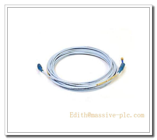
330130‑075‑00‑05
Key Specifications
| Parameter | Value |
|---|---|
| Part Number | 330130‑075‑00‑05 |
| Series | 3300‑XL 8 mm Microdot Proximity Transducer System |
| Cable Construction | Non‑armored 75 Ω tri‑axial coaxial, FEP insulation |
| Nominal Length | 7.5 m |
| Connector Type | Right‑angle Microdot 10‑32 coaxial (both ends) |
| DC Resistance | 0.88 ± 0.13 Ω |
| Operating Temperature Range | ‑51 °C ~ +177 °C |
| Minimum Static Bending Radius | 50 mm; avoid sharp kinks, especially near right‑angle connector housings |
| Outer Jacket Material | FEP fluoropolymer, oil‑mist resistant |
| Shielding | Double‑layer tri‑axial shielding for EMI/RFI noise suppression |
| Certifications | API‑670 compliant; check hardware label for IS / ATEX rating |
| Country of Origin | USA |
| Weight | ≈0.24 kg |
Main Features
- Dual‑end right‑angle Microdot 10‑32 connectors: Optimized for tight‑space cabinet / junction‑box / machine‑case routing, eliminates physical collision risk for straight‑style connectors.
- 7.5‑meter non‑armored standard‑grade tri‑axial cable: Modular calibrated segment to build correct total transducer‑loop length for Microdot‑based 3300‑XL 8 mm systems.
- Tri‑axial double‑shielded structure: Strong immunity against noise interference from VFD, contactors and high‑power AC wiring, preserves eddy‑current signal integrity.
- FEP fluoropolymer insulation: Resists turbine oil‑mist, chemical contamination and wide industrial temperature swings.
- Factory‑molded right‑angle Microdot assemblies: Consistent impedance performance, vibration‑resistant for long‑term turbomachinery continuous service.
- Full interoperability within 3300‑XL Microdot transducer ecosystem; API‑670 compliance for turbomachinery protection loops.
Typical Application Scenarios
- Signal extension for 3300‑XL Microdot‑interface 8 mm proximity probes (e.g. 21508‑02‑12‑05‑02) with limited installation clearance for straight Microdot connectors
- Radial shaft‑relative vibration monitoring, axial thrust‑position protection and Keyphasor phase‑reference signal transmission on steam turbines, gas turbines and centrifugal compressors
- Refinery, petrochemical and power‑plant sites deploying 3500 rack‑based monitoring or Microdot‑variant 990 transmitters
- Overhaul spare‑part replacement for existing medium‑length right‑angle Microdot transducer loops
- Retrofit projects where cabinet / junction‑box installation space is highly restricted and medium cable‑run length is required
Related & Recommended Alternative Models
| Model | Description |
|---|---|
| 330130‑075‑00‑00 | 7.5 m non‑armored extension cable, straight Microdot connectors both ends |
| 330130‑075‑01‑05 | 7.5 m armored extension cable, dual‑end right‑angle Microdot |
| 330130‑085‑00‑05 | 8.5 m non‑armored, right‑angle Microdot variant |
| 330190‑080‑00‑00 | 8 m ETR high‑temperature straight‑Microdot extension cable (higher temperature rating) |
| 330930‑075‑00‑RU | 7.5 m NSv ClickLoc extension cable (incompatible, reference‑only comparison) |
Compatible Components & Accessories
- Proximity Probes: 21508‑xx‑xx‑xx‑02 and other 3300‑XL 8 mm Microdot‑interface probes
- Monitoring Hardware: 330180‑xx‑00 proximitor modules, Bently Nevada 3500 rack system, Microdot‑type 990‑series transmitters
- Casing‑penetration fitting: 43501‑02‑04‑02 low‑pressure cable‑seal assembly and 43574‑04 multi‑hole grommet
- Installation consumables: Cable clamps for strain‑relief, high‑temperature cable ties, cable glands
- Tooling: Specified‑torque Microdot connector tightening tool
- Calibration tool: 8 mm 3300‑XL static gap calibration fixture
Installation and Configuration Guide
Warning: Installation must be performed by qualified instrument technicians. Always refer to original Bently Nevada 3300‑XL transducer‑system manual as primary reference. Verify intrinsic‑safety marking before deployment in explosive classified hazardous zones.
- Pre‑installation Total‑Length Calculation
- Calculate total transducer length = probe integral pigtail length + 7.5 m of this extension cable.
- Confirm total length exactly matches calibrated‑length requirement of installed proximitor or transmitter. Length mismatch will produce scale‑factor error.
- Cable Routing Requirements
- Route tri‑axial cable separately from high‑power AC, VFD and contactor wiring to minimize EMI noise.
- Maintain minimum static bending radius ≥50 mm. Avoid sharp bends especially near right‑angle connector housings. Do not pull cable assembly by connectors.
- Where cable passes through machine‑case wall, install approved cable‑seal assembly (43501‑02‑04‑02) to prevent mechanical crush and oil‑mist ingress.
- Right‑Angle Microdot Connector Mating Procedure
- Clean Microdot contact surfaces before mating. Align pin‑keyway correctly, tighten to manufacturer‑specified torque value. Do not over‑torque right‑angle connector housing.
- Install strain‑relief clamps within short distance of each right‑angle connector, to eliminate mechanical bending stress transferred onto connector joints.
- System Commissioning
- Complete full transducer‑loop assembly and power‑up proximitor / monitor hardware.
- Read static gap voltage to verify probe mechanical gap setting. Perform static‑gap calibration test with 8 mm calibration fixture to validate system scale‑factor.
- Confirm Not‑OK fault status clears after proper wiring and gap adjustment.
- Maintenance & Troubleshooting
- During machinery turnaround, inspect right‑angle Microdot connectors for oil contamination, dirt and corrosion; check FEP jacket for cracking or oil‑swelling.
- Unstable gap‑voltage readings, high noise level or persistent Not‑OK faults may indicate damaged cable, loose Microdot joint or incorrect total‑system cable length.
- If cable assembly is damaged, replace complete factory cable assembly; field splicing or repairing tri‑axial coaxial cable is prohibited.
Supplementary Remark
330130‑075‑00‑05 is a 7.5‑meter non‑armored standard‑grade tri‑axial extension cable for 3300‑XL 8 mm Microdot transducer systems, fitted with dual‑end right‑angle Microdot‑10‑32 connectors for space‑limited installation scenarios with medium‑length cable‑run demand. It is incompatible with NSv ClickLoc and ETR‑series extension cables. Before commissioning, cross‑check total transducer‑system length, right‑angle connector style, temperature rating and intrinsic‑safety requirement against project BOM and mechanical drawings.



 Start Chat




