
Description
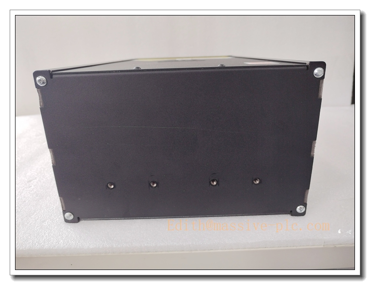
Advanced Energy APEX3013 (3156114-746) 3000W 13.56 MHz RF Plasma Generator
Product Core Introduction
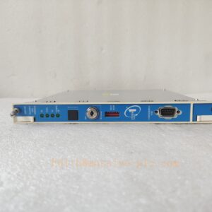
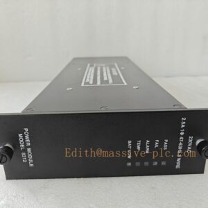
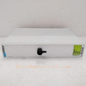
The APEX3013, part number 3156114-746, is a high-density solid-state RF plasma generator manufactured by Advanced Energy within the APEX series. Operating at 13.56 MHz with a rated output power of 3000W, this unit delivers highly stable RF power for plasma processes in semiconductor and thin-film manufacturing. It integrates embedded control circuitry, real-time power regulation, reflected power monitoring and multi-level fault interlock protection. Featuring compact chamber-mount construction, fast closed-loop response and optional pulsing capability, the generator maintains consistent plasma conditions across wafer etch, deposition and chamber cleaning recipes. This model is end-of-life from the original OEM and supplied as tested refurbished / surplus spare equipment for legacy fab production tools.
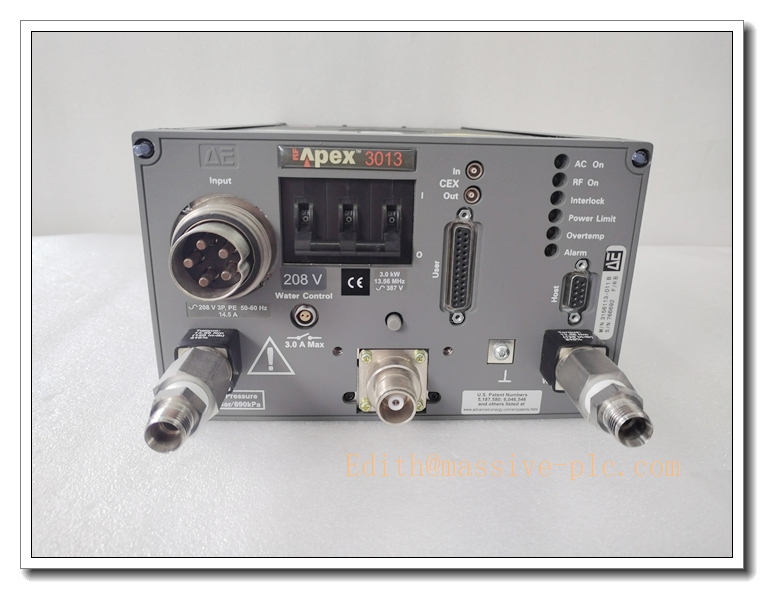
APEX3013 3156114-746
Main Technical Specifications
| Technical Parameter | Specification Value |
|---|---|
| Model / Part No. | APEX3013, 3156114-746 |
| Manufacturer | Advanced Energy |
| RF Frequency | 13.56 MHz ±0.005% |
| Rated Output Power | 3000 W (3kW) |
| Power Regulation Mode | Constant Power / Constant Voltage / Constant Current |
| Reflected Power Protection | Adjustable threshold, arc detection & shutdown |
| Power Input | 208 VAC, 3-phase, 50/60 Hz |
| Control Supply | 24 VDC auxiliary control input |
| Communication Interface | Analog I/O, Serial / OEM proprietary tool bus |
| Operating Temperature | 10 ℃ ~ +50 ℃ (Cleanroom environment) |
| Storage Temperature | -40 ℃ ~ +85 ℃ |
| Operating Humidity | 5% ~ 85% RH, non-condensing |
| Mounting Style | Chamber / On-tool mount |
| Dimensions | 330 mm × 220 mm × 110 mm |
| Net Weight | 12.7 kg |
| Compliance | SEMI S2, CE, SEMI F47 |
| Lifecycle Status | OEM Discontinued, available as aftermarket tested spare |
Brand Same‑Series Model Recommendation
- APEX1513 (3156110-XXX): 1500W 13.56MHz RF generator, lower power variant, for low-to-medium power etch and deposition processes, compact footprint.
- APEX3013 (3156114-748): Same 3kW platform, alternate revision variant, pin and form-factor drop-in compatible, minor firmware difference.
- APEX4013: 4000W high-power APEX series generator, upgraded power stage for high-density plasma and high-rate chamber cleaning.
- NAVIGATOR 3013: Newer AE RF platform, digital control architecture, recommended for long-term system migration replacing legacy APEX3013.
Professional Quality Control Test Standard Operating Procedures (SOP)
5.1 Incoming Component & Visual Inspection
All internal power transistors, RF transformers, capacitors, control PCBs and connectors are inspected against AE original BOM. Visual inspection checks for burnt traces, swollen capacitors, cracked solder and connector damage. Continuity and isolation tests are performed for high-current RF paths and safety interlock circuits.
5.2 Low-Power Power-On Pre-Test
Power the unit at reduced input voltage. Verify control board boot, LED status codes, communication handshake and self-diagnosis routines. Confirm no abnormal noise or thermal rise before applying RF output.
5.3 Burn-in & RF Stability Test
72-hour continuous burn-in in cleanroom ambient. Run cyclic power setpoint test with matched dummy load; log forward power, reflected power, frequency stability and temperature rise. Units with power drift, intermittent RF dropout or false arc triggers are rejected.
5.4 Full Calibration & Performance Test
Use calibrated RF power meter, dummy load and signal analyser to calibrate power accuracy, linearity, response speed and arc detection threshold. Validate all protection functions: over-power, over-temperature, high reflected power, emergency stop interlock.
5.5 Environmental Stress Screening
Temperature cycling (10 ℃ ↔ +50 ℃), humidity soak and low-level random vibration per IEC 60068 to verify mechanical integrity and RF stability under simulated shipping and fab operating stress.
5.6 Final System Acceptance Test
Integrate the generator with matching RF match network and chamber controller. Execute full recipe simulation, communication handshake, alarm sequence and emergency shutdown test. Complete label, appearance and accessory check. Only fully validated units are packed for shipment.
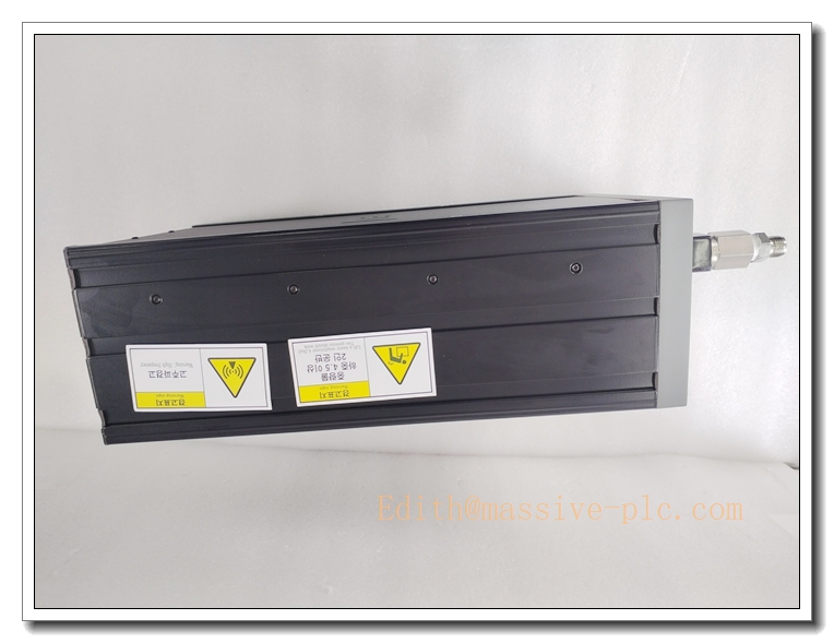
APEX3013 3156114-746
New Module / Generator Installation Guidelines
6.1 Pre-Installation Preparation
- Lock-out/tag-out (LOTO) the 3-phase mains supply and confirm complete power removal. Discharge all high-voltage capacitors inside the unit and RF match network.
- Wear anti-static wristband and gloves, use anti-static mat for handling internal PCBs.
- Inspect APEX3013 for physical damage, burnt components, connector pin bending. Confirm compatibility with existing match network and host tool controller.
- Check cooling airflow path, filter condition and cable routing clearance.
6.2 Hardware Installation
- Mount the RF generator securely on chamber/tool frame with specified torque for mounting fasteners.
- Connect 3-phase AC mains, 24VDC control power, interlock wiring and tool communication harness strictly following AE wiring diagram.
- Attach RF coaxial output cable between generator and matching network; properly torque RF connector and verify ground bonding.
- Confirm cooling air inlet and outlet are unobstructed.
6.3 Post-Installation Commissioning
- Double-check wiring, ground connections and interlock loop continuity before energizing.
- Apply 24VDC control power first; run unit self-test, confirm no hardware fault codes.
- Power on 3-phase mains, perform dummy load low-power RF test, verify power output and reflected power reading.
- Connect to chamber match network, run recipe step-up power test, tune match network and validate arc handling.
- Run continuous process simulation for 30–60 minutes before returning to wafer production.
Important Safety Note: This equipment contains high RF energy and high voltage. Only qualified semiconductor service technicians may perform installation and service.
Application Scenarios & Product Characteristics
7.1 Application Scenarios
- Semiconductor wafer processing: Plasma Etching, PECVD, PVD, HDP-CVD, PEALD, ALE
- Semiconductor chamber plasma cleaning
- Flat panel display and solar cell thin-film deposition
- Vacuum plasma surface treatment for advanced materials
7.2 Key Characteristics
- 3000W high power density, compact chamber-mount design saving tool footprint
- Fast digital closed-loop power control for excellent plasma recipe repeatability
- Integrated arc detection and fast shutdown to protect chamber hardware
- Wide dynamic range for low-power to full-power process recipes
- Analog and digital communication interfaces for integration with OEM semiconductor tools
- Rugged cleanroom-grade design supporting 24/7 continuous production operation
- Critical spare part for legacy fabrication tools (OEM end-of-life)
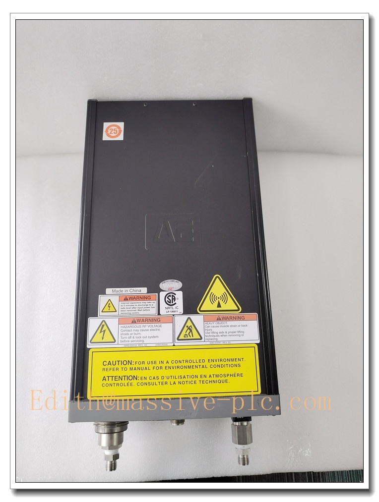
APEX3013 3156114-746
FAQ (Frequently Asked Questions)
A1: Check emergency stop interlock loop continuity, 24VDC control supply and fault status codes. Verify match network connectivity, RF cable integrity and interlock reset sequence.
Q2: High reflected power alarm triggers during plasma process. A2: Inspect RF coaxial cable, connector oxidation, match network tuning and chamber condition. Check for chamber contamination, dielectric breakdown or plasma instability. Re-tune match network for the target recipe.
Q3: Power output drifts during long process runs. A3: Check cooling airflow and filter clogging. Verify internal component thermal drift. Run power calibration; inspect aging capacitors and power semiconductors.
Q4: Tool controller cannot communicate with the generator. A4: Check communication harness pin integrity, cable shielding and grounding. Confirm firmware revision compatibility between generator and host tool controller.
A5: No. This model is discontinued by Advanced Energy. Stock is limited to tested refurbished / surplus aftermarket inventory.
Q6: Can I hot swap this generator while the tool is energized? A6: NOT PERMITTED. High voltage and RF hazard. Always perform LOTO and full capacitor discharge before removal or installation.


 Start Chat




