
Description
350-E-P1-G1-H-E-S-C-P-2E-D Digital Vibration & Position Monitor for Rotating Machinery Protection System
Core Product Overview
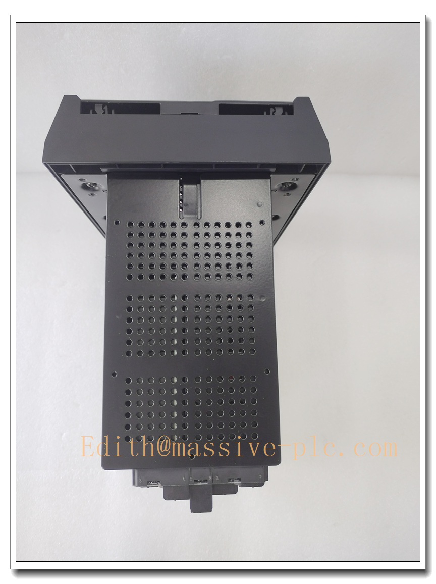
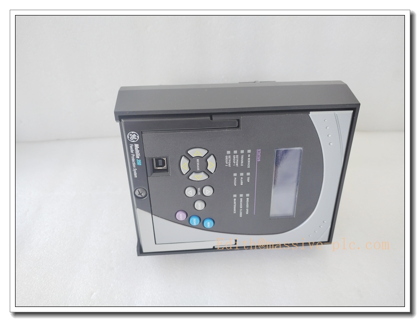
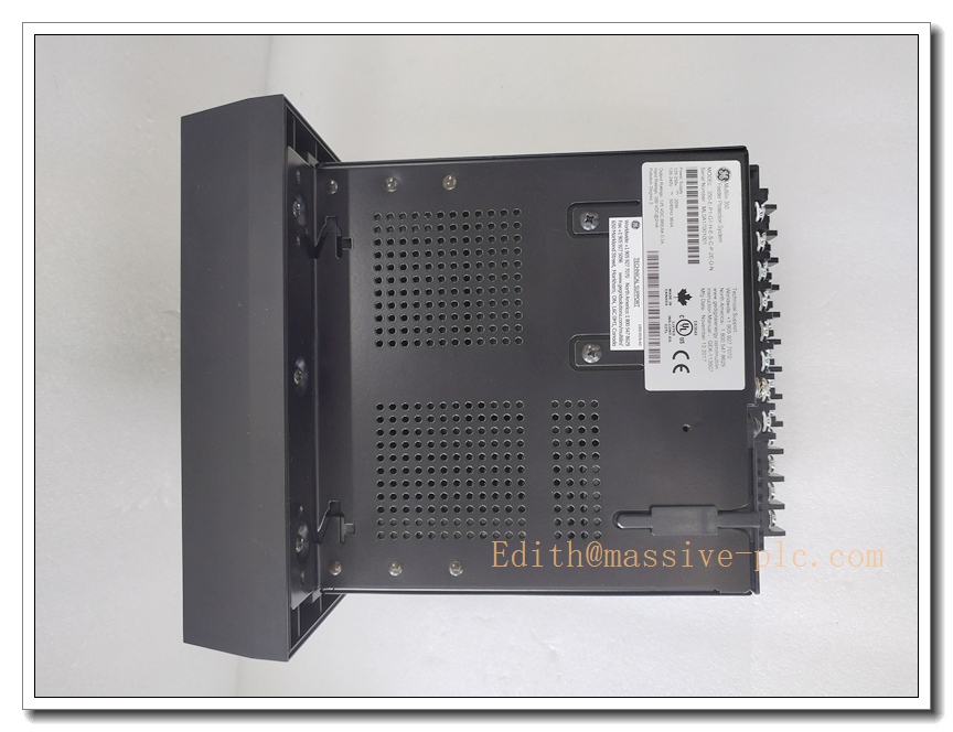
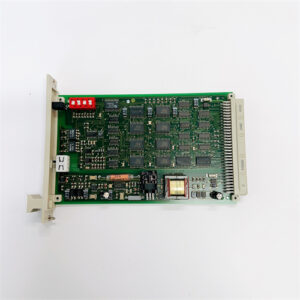
The 350-E-P1-G1-H-E-S-C-P-2E-D is a configurable rack-mounted machinery monitor used for continuous online measurement, alarm and protection of rotating equipment parameters including shaft vibration, radial displacement, thrust position and speed. It accepts input signals from eddy current proximity probes and velocity transducers, processes real-time dynamic data, provides configurable alarm and trip relay outputs, analog retransmission signals and digital communication to DCS/PLC systems. This fully configurable model is built for critical turbomachinery such as steam turbines, gas turbines, compressors and large pumps. It is a legacy industrial monitoring module, commonly supplied as surplus, bench-tested refurbished spare parts for power, oil & gas and petrochemical plants. The long hyphenated string represents a full configuration code defining power supply, input types, relay options, communication protocol, enclosure and certification variants.
350-E-P1-G1-H-E-S-C-P-2E-D
Main Technical Specifications
- Part Number: 350-E-P1-G1-H-E-S-C-P-2E-D
- Device Type: Multi-Parameter Machinery Protection Monitor
- Signal Input: Eddy current probe input for shaft displacement / vibration; velocity transducer input for casing vibration
- Power Supply: 24 VDC industrial control power
- Measurement Functions: Radial vibration, thrust position, rotor speed, phase reference
- Analog Output: Isolated 4–20 mA retransmission for each channel, configurable range
- Relay Outputs: Independent configurable Alert and Danger trip relays, latch/non-latch selectable
- Communication Interface: RS485 Modbus RTU for host SCADA and DCS integration
- Local Indication: LED status indicators for channel fault, alert and danger trips
- Mounting: Standard 19-inch rack slot, backplane connection
- Operating Temperature: -20°C ~ +60°C
- Humidity: 5%–95% non-condensing
- Shock & Vibration: Compliant with API 670 industrial machinery monitoring standards
- Certifications: CE, CSA
- Status: Obsolete original OEM production; available stock consists of surplus and professionally refurbished units
Same-Series Model Recommendations (8 Models)
- 350-E-P1-G1-H-E-S-C-P-2E-D: Full-featured vibration and position monitor (subject model)
- 350-E-P1-G0-H-E-S-C-P-2E-D: Basic version without high-speed phase measurement function
- 350-E-P2-G1-H-E-S-C-P-2E-D: Variant with universal AC/DC auxiliary power input
- 350-E-P1-G1-L-E-S-C-P-2E-D: Low-density relay version with fewer alarm output contacts
- 350-E-P1-G1-H-E-S-E-P-2E-D: Ethernet Modbus TCP communication option instead of RS485
- 350-E-P1-G1-H-N-S-C-P-2E-D: Non-latching relay configuration for non-critical auxiliary machines
- 350-E-P1-G1-H-E-S-C-P-1E-D: Early hardware revision with older firmware and limited diagnostic logs
- 350-E-P1-G1-H-E-T-C-P-2E-D: Transducer-only version optimized for casing velocity vibration monitoring
Professional Quality Control & Testing Standard Operating Procedures
All surplus and refurbished 350-E-P1-G1-H-E-S-C-P-2E-D monitors follow this inspection workflow:
- Visual & Backplane Inspection: Examine front panel LEDs, PCB, terminal connectors and backplane pins for corrosion, burn marks, bent pins or component damage; verify full configuration label integrity.
- Power Supply Bench Test: Apply rated 24VDC supply, confirm stable internal voltage rails and no power fault indication.
- Channel Input Simulation: Inject calibrated eddy current and velocity transducer signals to verify measurement accuracy across configured ranges.
- Alarm & Trip Relay Test: Set alert and danger thresholds, confirm relay pickup, dropout and latch behaviour matches configuration.
- 4–20mA Analog Output Calibration: Validate zero and full-scale current output for each measurement channel.
- Modbus Communication Test: Poll register values via RS485 Modbus RTU simulator to confirm data publishing and fault register reporting.
- Diagnostic & Fault Injection Test: Simulate probe break, short circuit and signal out-of-range to verify channel fault detection.
- Final Cleaning & Packaging: Clean backplane contacts and PCB assembly, reset configuration to factory default, apply ESD protection with printed test certificate.
350-E-P1-G1-H-E-S-C-P-2E-D
New / Refurbished Monitor Installation Guidelines
- Pre-Installation Safety: Execute lockout-tagout procedures; isolate rack control power, probe extension cables and all trip relay wiring to prevent unintended machine trips.
- Rack and Backplane Check: Verify compatible backplane type, proper grounding and adequate cabinet ventilation; avoid mounting adjacent to high-current power modules.
- Mechanical Mounting: Insert module firmly into the designated 19-inch rack slot, engage backplane connector completely and fasten front panel retaining screws without over-tightening.
- Field Sensor Wiring: Route eddy current probe extension cables separately from high-power control cables to reduce EMI; terminate shield grounding per OEM drawing requirements.
- Module Configuration: Set measurement ranges, probe sensitivity, alert/danger setpoints, relay latch mode and Modbus node address using supporting configuration software.
- Pre-Commissioning Functional Test: Power on without rotating machinery; simulate sensor signals to verify readings, LED status, analog outputs and relay action.
- System Commissioning: Perform slow roll and run-up test on the machine, confirm baseline vibration and thrust position readings, save configuration file and test trip logic in a safe offline state.
Application Scenarios & Product Features
Typical Application Scenarios
- API 670 machinery protection systems for steam and gas turbine packages
- Centrifugal and axial process compressors in oil, gas and petrochemical facilities
- Large critical pumps, fans and blowers in power generation plants
- Shaft thrust position and radial vibration protection for high-speed rotating equipment
- Retrofit spare replacement for existing 350 series rack-based monitoring systems
- Turbomachinery condition monitoring and predictive maintenance programs
Core Product Features
- Multi-channel measurement for shaft vibration, thrust position, speed and phase angle
- Direct interface with standard eddy current proximity probes and velocity sensors
- Independent alert and danger relay outputs for machinery protection logic
- Isolated 4–20mA analog retransmission for continuous trending in DCS/SCADA
- RS485 Modbus RTU digital communication for remote data access and diagnostics
- Rack-mounted modular design for flexible system expansion and spare replacement
- Built-in sensor fault detection for probe open/short circuit and cable integrity
- Compliant with API 670 requirements for critical rotating machinery protection
Frequently Asked Questions (FAQ)
Q1: What does the long hyphenated part number 350-E-P1-G1-H-E-S-C-P-2E-D represent? A1: Each segment in the dash-separated code defines hardware options including power supply type, input signal groups, relay configuration, communication type, firmware revision and certification. This full part number identifies the exact variant of the monitor.
Q2: Is the 350-E-P1-G1-H-E-S-C-P-2E-D still in active OEM production? A2: No, this 350 series monitor is obsolete. Available inventory is surplus used or professionally refurbished and fully bench tested.
Q3: Can this module be used with any brand of eddy current probe? A3: It can work with standard eddy current proximity probes, but probe sensitivity must be matched and configured in software; mismatched sensitivity will produce incorrect vibration and position readings.
Q4: What are the common failure modes for this monitor? A4: Typical failures include ageing on-board power capacitors, backplane pin corrosion, analog circuit drift, relay contact wear after many trip cycles, and configuration memory corruption after uncontrolled power loss.
Q5: Can the module be hot-swapped in an energized protection rack? A5: Hot swap is not recommended. While some racks support hot insertion, relay state changes may trigger machine trips. Isolate control power and lock out trip circuits before removal or replacement.


 Start Chat




