Description
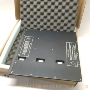
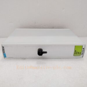
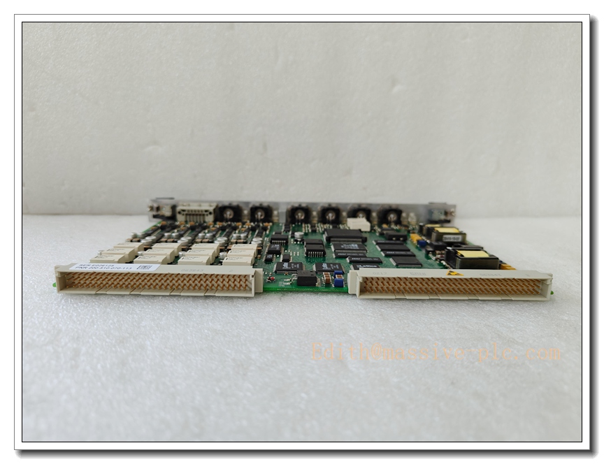
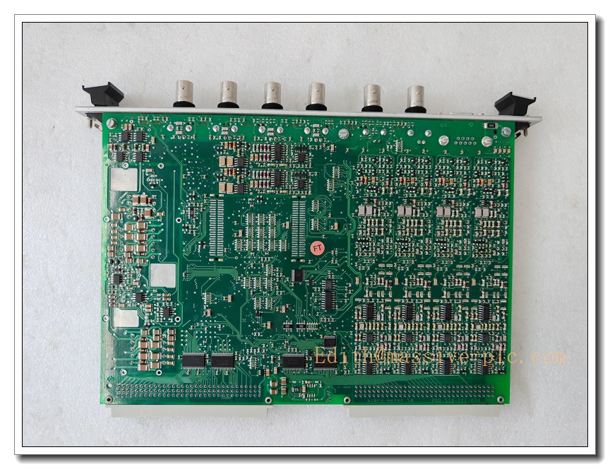
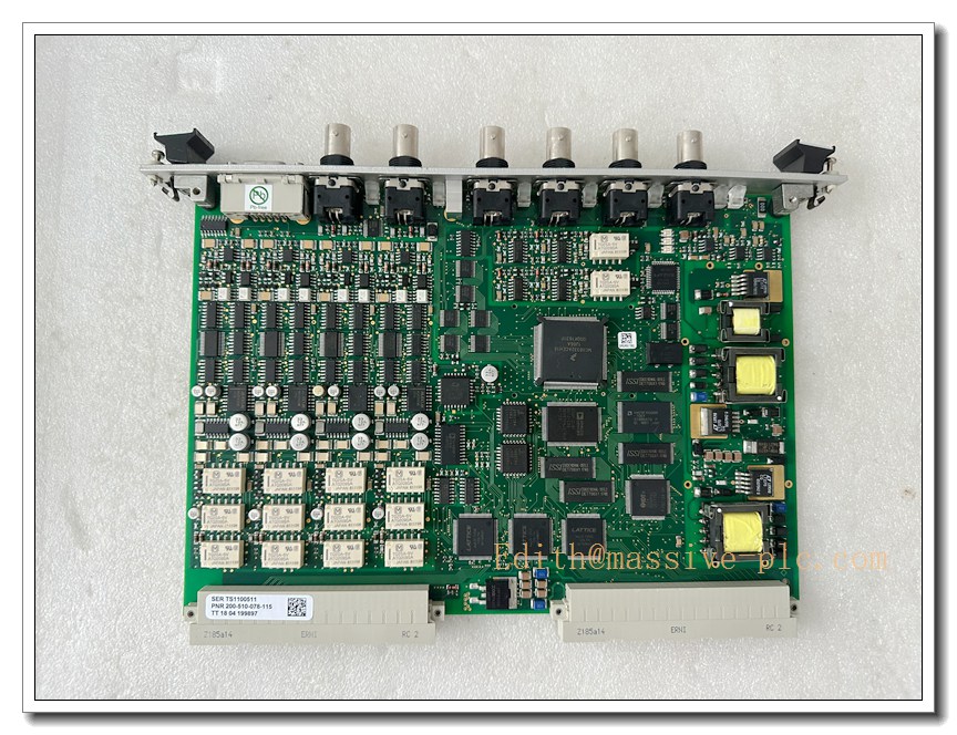
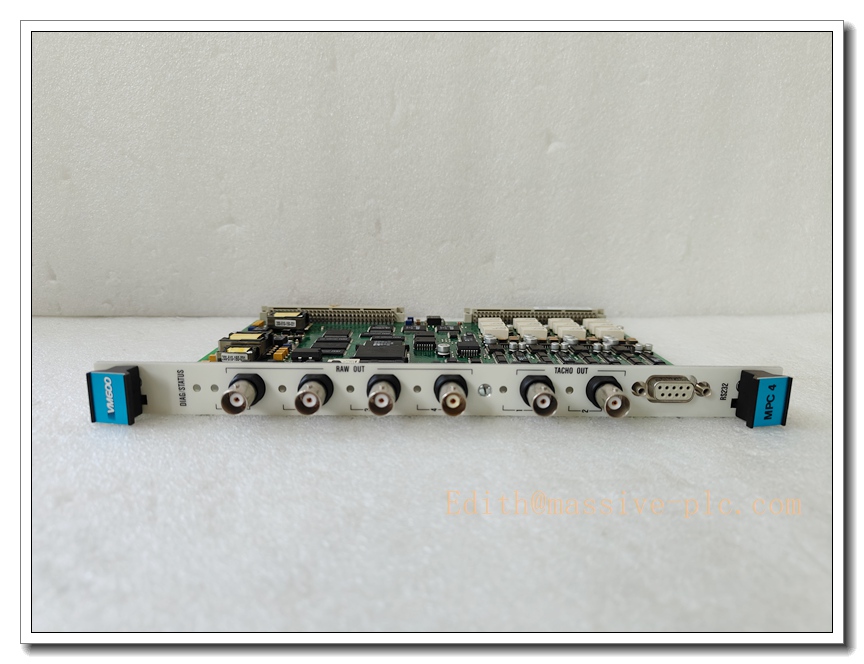
Meggitt MPC4 200-510-071-113 / 200-510-SSS-1HH Multi-Channel Process Control Module
Product Overview
The Meggitt MPC4 is a high-performance, rugged multi-channel process control module engineered for critical machinery protection and condition monitoring systems. Designed to deliver reliable signal acquisition, processing and output for rotating equipment, it processes sensor inputs in real time to monitor vibration, speed, temperature and displacement parameters. This unit provides high integrity measurements and alarm logic for turbomachinery, meeting strict industrial safety requirements for continuous operation in harsh environments. The variant 200-510-071-113 and 200-510-SSS-1HH support configurable I/O interfaces, stable long-term operation and seamless integration within Meggitt monitoring racks.
Meggitt MPC4 200-510-071-113/200-510-SSS-1HH
Key Technical Specifications
- Product Family: MPC4 Multi-Channel Process Control Module
- Part Numbers: 200-510-071-113, 200-510-SSS-1HH
- Input Types: Vibration, proximity, speed, temperature analogue sensor inputs
- Signal Processing: High-resolution real-time data sampling and filtering
- Power Supply: Standard backplane powered, compliant with Meggitt rack power specification
- Operating Temperature Range: -20°C to +70°C
- Enclosure: Plug-in rack mount module, hot-swappable compatible (system dependent)
- Communication: Internal backplane bus for data exchange with rack controller
- Safety Rating: Designed for machinery protection applications, meets industrial reliability standards
- Mounting: Standard 3U rack slot installation
- Diagnostics: Built-in module self-test, sensor fault detection, wire break monitoring
- Data Output: Configurable relay alarm outputs and analogue value transmission
Recommended 8 Similar Series Models
- Meggitt MPC4 200-510-071-111
- Meggitt MPC4 200-510-071-112
- Meggitt 200-510-071-114
- Meggitt 200-510-SSS-1HA
- Meggitt 200-510-SSS-1HB
- Meggitt 200-510-SSS-1HC
- Meggitt 200-510-072-113
- Meggitt 200-510-073-113
Quality Control & Test Standard Operating Procedure (SOP)
- Visual Inspection: Examine PCB, connectors, front panel and housing for physical damage, scratches, solder defects and label integrity. Verify part number and revision marking match documentation.
- Continuity & Insulation Test: Perform continuity check on all pin terminals; conduct insulation resistance test between power circuits and signal circuits to eliminate short circuit risk.
- Power-Up Functional Test: Apply rated rack power gradually. Check power consumption, LED indicator status and boot sequence. Confirm no overheating or abnormal noise.
- Self-Diagnostic Test: Trigger built-in module self-test routine. Confirm all internal diagnostic routines pass without fault codes.
- Signal Input Calibration: Inject standard reference signals to each input channel. Validate measured readings, linearity, gain accuracy and filtering performance.
- Alarm & Relay Output Test: Simulate threshold exceed conditions to verify alarm activation, relay switching timing and contact integrity.
- Backplane Communication Test: Install module into compatible rack, validate stable bus communication, data upload and parameter configuration.
- Environmental Burn-in Test: Run continuous burn-in at rated operating temperature for specified duration to screen early failure components.
- Final Functional Recheck: Repeat core function tests after burn-in. Generate test report and serial number traceability record before shipment.
New Module Installation Guide
- Pre-Installation Preparation: Power down the monitoring rack completely. Verify ESD protection measures (ground wrist strap, anti-static mat). Confirm the module part number matches the required configuration.
- Rack Slot Preparation: Check the target rack slot backplane connector for dirt, bent pins or corrosion. Clear obstructions from the module guide rails.
- Module Insertion: Align the module with rack guide rails. Slide the module smoothly into the slot until the backplane connector fully engages. Tighten front panel fixing screws evenly.
- Wiring Verification: Confirm all external sensor and output wiring follows wiring diagrams. Check cable shielding and grounding connections.
- Power On: Restore rack power supply. Observe front panel LEDs to confirm normal boot status.
- Configuration & Commissioning: Log into the system software, load correct parameter set, set alarm thresholds. Run channel test to confirm sensor signal reception.
- Post-Installation Check: Execute system self-test. Confirm no active fault alarms. Document installation and commissioning records.
Application Scenarios & Features
Application Scenarios
- Gas turbine and steam turbine machinery protection systems
- Centrifugal & axial compressor condition monitoring
- Industrial turbo-generator sets
- Heavy-duty rotating equipment in petrochemical, power generation, offshore energy plants
- Critical pump and fan vibration monitoring
Core Features
- Multi-channel synchronous signal acquisition for multi-point machinery monitoring
- Integrated sensor fault detection for improved system availability
- Rugged construction for high vibration and wide temperature industrial environments
- Configurable alarm thresholds for early warning of equipment deterioration
- Rack-based modular design, easy maintenance and component replacement
- High measurement stability for long-term continuous monitoring
- Digital backplane communication for centralized data collection
MPC4 200-510-SSS-1HH
FAQ
Q1: What is the difference between 200-510-071-113 and 200-510-SSS-1HH?
A1: These two variants differ in internal firmware, channel configuration and terminal assignment. 200-510-071-113 is fixed configured version while 200-510-SSS-1HH is a special configurable variant. Always verify the original BOM and rack software compatibility before replacement.
Q2: Can I hot-swap the module while the rack remains powered?
A2: Hot swap capability depends on your full rack system configuration. Check the system manual. Even if hot-swap is supported, avoid hot replacement during critical machine running phases.
Q3: What should I do if the module reports channel fault after installation?
A3: Check sensor cable integrity, wiring polarity and shielding. Run module self-test. Swap the module to a known good slot to isolate whether the fault comes from the module, wiring or sensor.
Q4: Does this module support SIL rated machinery protection?
A4: The overall SIL rating belongs to the complete machinery protection system, not the standalone module. Full system assessment is required to achieve target SIL level.
Q5: How long is the service life and recommended calibration interval?
A5: Typical service life under normal operating environment is 10+ years. Recommended calibration cycle is 12 to 24 months, subject to site safety specification.
Q6: Is this module backward compatible with older Meggitt rack systems?
A6: Compatibility depends on rack backplane hardware revision and host firmware version. Confirm compatibility matrix before replacement.
Q7: What ESD precautions must be followed during handling?
A7: Always use grounded anti-static wrist strap and anti-static surface. Do not touch connector pins directly. Keep module inside anti-static bag until installation.
Q8: Can I modify alarm threshold parameters locally on the module?
A8: Parameters are configured via the rack host software, not on the module front panel. All threshold settings are downloaded to through backplane communication.