
Description
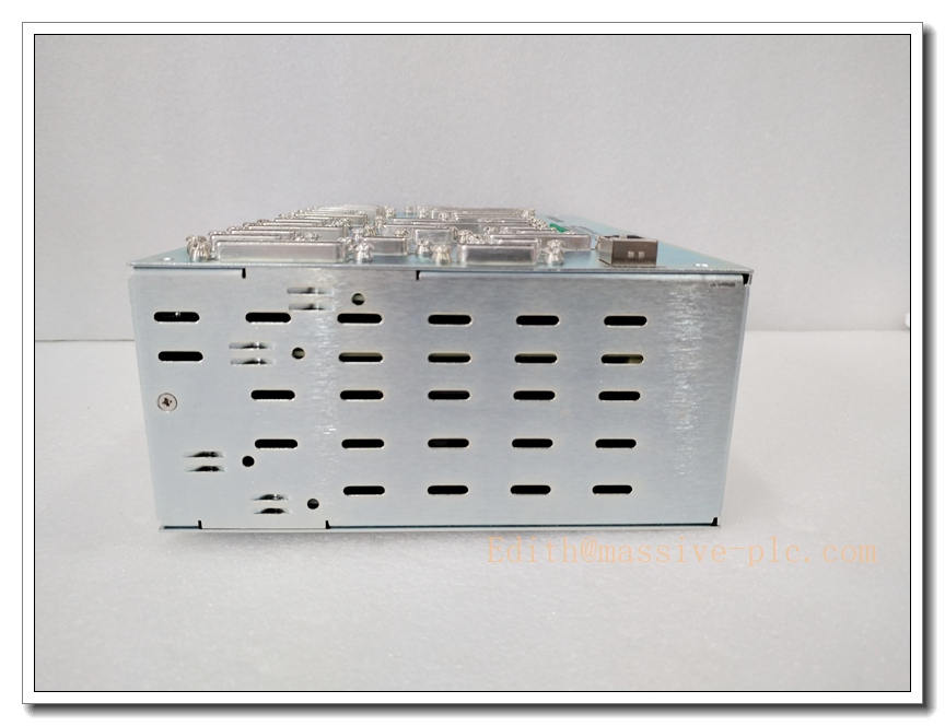
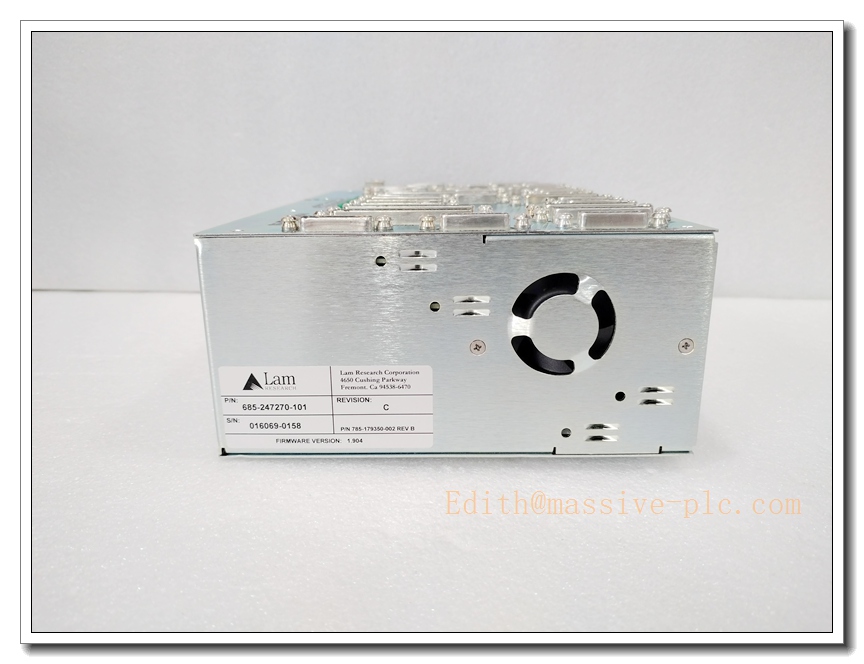
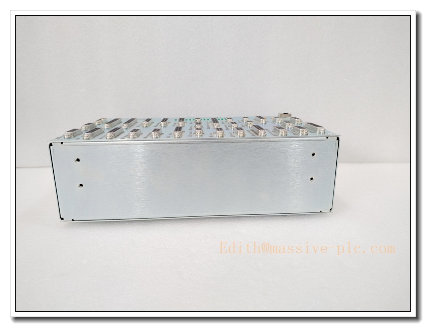
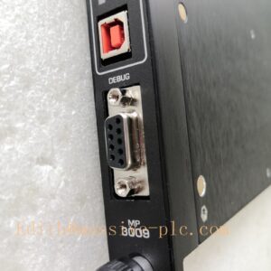
LAM 685-247270-101 Main Console I/O Controller Assembly, Semiconductor Etch Tool System Interface Unit
Product Description
The 685-247270-101 is a main console I/O controller assembly manufactured by Lam Research for Kiyo and 2300 Flex plasma etch semiconductor platforms. It acts as the central signal bridge between the tool host CPU, chamber subsystems, local HMI, safety interlocks, pneumatic actuators and auxiliary sensors. The assembly integrates digital input/output, analog signal conditioning, fault latching and watchdog supervision. With conformal-coated circuit boards, it is engineered for cleanroom operation, resisting humidity, trace fluorine-based plasma byproducts and mechanical vibration. It processes recipe-related interlock logic, distributes setpoints to chamber sub-modules, and forwards diagnostic and alarm data to the tool host software. This unit is a critical spare for tool console control, governing machine state readiness, safety permissives and local operator interface functions.
Technical Parameters
| Item | Specification |
|---|---|
| Manufacturer | Lam Research |
| Model | 685-247270-101 |
| Function | Main Console I/O Controller Assembly |
| Power Supply | 24 VDC cleanroom auxiliary supply; isolated 5 VDC for logic circuits |
| Signal Types | 24VDC DI/DO, 4–20mA analog, safety interlock latching signals |
| Host Interface | Proprietary internal tool backplane bus |
| Onboard Diagnostics | Watchdog timeout, short-circuit detection, interlock fault logging, power rail monitoring |
| PCB Protection | Conformal coating for corrosive process byproduct resistance |
| Mounting | Console cabinet rack-mount assembly |
| Operating Temperature | 15 ℃ ~ 60 ℃ |
| Humidity | 10–85% RH, non-condensing |
| Compliance | SEMI S2 semiconductor equipment safety standard |
| Weight | Approx. 1.1 kg |
| Status Indication | LED arrays for power, bus communication, interlock status and channel alarms |
Recommended Related Models (8 units)
- 685-247270-001: Base revision of the main console I/O controller
- 810-102361-222: Rocker valve interface PCB for chamber vacuum control
- 853-150806-001: OES optical emission spectrometer for plasma endpoint detection
- 810-114278-001: RF match control board for ICP plasma source
- 810-078432-001: Chamber door safety interlock PCB
- 810-002876-001: Chamber main system controller motherboard
- 853-045976-001: Rocker valve actuator assembly with Hall position sensor
- LAM Host Console HMI Panel: Local operator touchscreen paired with this I/O controller
LAM 685-247270-101
Compatibility & Installation Traps
Compatibility
- Primary host platforms: Lam Research Kiyo, 2300 Flex plasma etch systems
- Control software: Lam fab host recipe execution and fault monitoring framework
- Field devices: Console safety switches, emergency stop loops, pneumatic valve banks, pressure and temperature transmitters
- Note: It uses Lam proprietary tool bus; it is not compatible with standard PLC Modbus or EtherCAT networks.
Critical Installation Traps
- Revision & Firmware Matching: Hardware revision and embedded firmware must match the tool’s installed host software. Mismatch can cause missing interlock permissives, unresponsive HMI or recipe abort.
- Safety Interlock Wiring Polarity: E-stop and chamber door interlock loops are hardwired through this assembly. Incorrect wiring defeats safety permissives and creates hazardous operating states.
- Conformal Coating Integrity: Never scrape or peel conformal coating during ESD handling. Damaged coating exposes copper traces to fluorine byproducts and leads to intermittent signal drift.
- ESD Sensitivity: The controller assembly contains high-density logic and signal conditioning circuits. All disassembly and replacement must be performed in an ESD-controlled cleanroom station.
- 24VDC Load Isolation: Shorted field actuators or solenoid coils can damage onboard output drivers. Isolate field loads before powering up the replacement assembly.
- Backplane Connector Pin Alignment: Bent pins on the internal backplane connector produce intermittent bus faults that are difficult to reproduce under static bench conditions.
- Cleanroom Contamination: Do not touch PCB traces or connector pins with bare skin. Oil residues cause leakage and long-term reliability degradation under heat and gas exposure.
- Interlock Reset Sequence: After replacement, the full safety interlock matrix must be verified and reset. Skipping validation may leave the chamber in an unsafe or locked-out state.
Standard Operating Procedure (SOP)
- Pre-installation inspection: Inspect the assembly housing, PCB coating and connectors for physical damage. Confirm part number and revision against the tool BOM.
- Lockout and energy isolation: Set the tool to safe state, purge process gases, de-energize console 24VDC auxiliary power and apply lockout/tagout.
- Mechanical removal: Remove cabinet covers, disconnect backplane bus, interlock harness and field I/O cables. Extract the old controller assembly from the rack slot.
- Reassembly and cabling: Seat the replacement unit in the rack, secure mounting fasteners. Reconnect all harnesses, verify pin assignment and latch all connectors.
- Power-up and self-test: Restore 24VDC auxiliary power. Check power, bus and interlock LED status. Execute the tool’s built-in I/O and watchdog diagnostic routine.
- Safety matrix validation: Test emergency stop, chamber door interlocks and all safety permissive circuits. Confirm fault latches trigger and clear as designed.
- Process qualification: Run dry chamber cycles, verify HMI control, setpoint distribution and alarm reporting. Release to production only after passing safety and recipe testing.
- Decommissioning: Isolate power before removal. Cap all connectors, pack the defective assembly inside ESD shielding bags for failure analysis or controlled disposal.
Application Scenarios
- Main console safety interlock and operator I/O control for Lam plasma etch chambers
- Recipe permissive logic and chamber subsystem signal distribution
- Emergency stop, chamber door and safety lockout supervision
- Cleanroom semiconductor wafer etch production tools
- Preventive maintenance replacement of aged console controller assemblies
- Troubleshooting of intermittent interlock faults and unresponsive local HMI
- Tool console subsystem retrofit and spare inventory support
- Diagnostic logging of chamber auxiliary sensor and actuator status
Supporting Components
- ESD wrist strap, ESD mat and anti-static shielding bags for cleanroom service
- Torque screwdriver set for rack mounting fasteners
- Replacement backplane connector contacts and wiring harness
- Lam tool service software and service login credentials
- Conformal coating touch-up repair kit
- Interlock loop test jig for safety matrix validation
- Filtered 24VDC cleanroom power supply with reverse polarity protection
- Spare console HMI operator touch panel



 Start Chat




