
Description
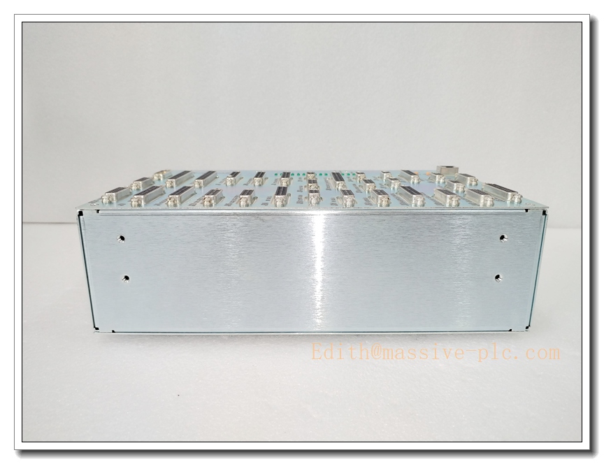
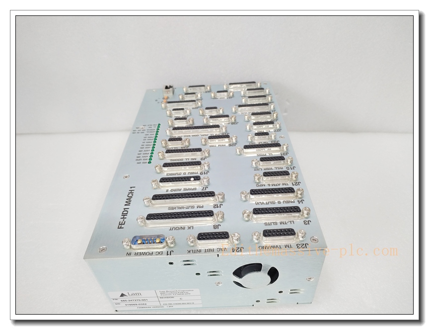
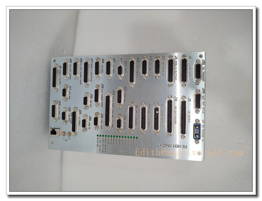
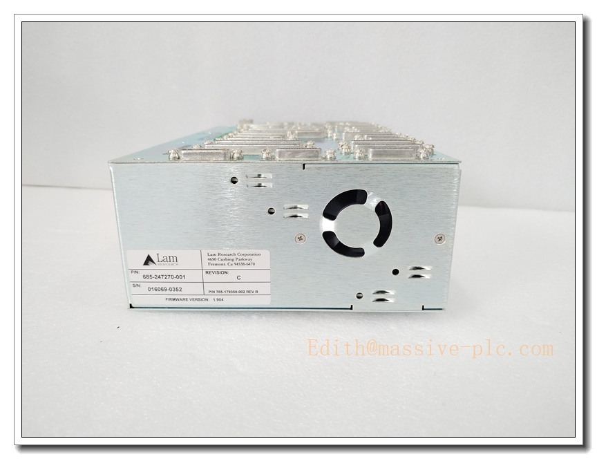
LAM 685-247270-001 FE-HD1 Mach1 Main Console I/O Controller Assembly, Semiconductor Etch Tool Safety & Field Signal Unit
Product Description
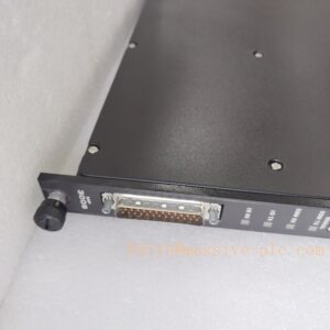
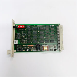
The 685-247270-001 is the base revision main console I/O controller assembly for LAM Research FE-HD1 Mach1 plasma etch platforms, the predecessor variant of 685-247270-101. It acts as the central signal gateway between the tool host CPU, local operator HMI, hardwired safety interlocks, pneumatic solenoids, pressure/temperature transmitters and auxiliary field sensors. This integrated assembly features digital I/O, analog signal conditioning, watchdog fault supervision and interlock latching logic. All internal circuit boards are conformal coated to withstand cleanroom conditions, including trace fluorine-based plasma byproducts, humidity and mechanical vibration. It executes safety permissive logic, routes recipe setpoints to chamber sub-modules, and uploads alarm and diagnostic logs to the fab host. It is a critical spare for console-level control, governing E-stop loops, chamber door interlocks and local machine readiness status.
Technical Parameters
| Item | Specification |
|---|---|
| Manufacturer | LAM Research |
| Model | 685-247270-001 (FE-HD1 Mach1) |
| Function | Main Console I/O & Safety Interlock Controller Assembly |
| Power Supply | 24 VDC cleanroom auxiliary supply; isolated 5 VDC logic rail |
| Signal Types | 24VDC DI/DO, 4–20mA analog, hardwired safety interlock latching signals |
| Host Interface | Proprietary internal tool backplane bus |
| Diagnostics | Watchdog timeout, over-current short detection, interlock fault latch, multi-rail power monitoring |
| PCB Protection | Conformal coating for corrosive process byproduct resistance |
| Mounting | Console cabinet rack slot assembly |
| Operating Temperature | 15 ℃ ~ 60 ℃ |
| Humidity | 10–85% RH, non-condensing |
| Compliance | SEMI S2 semiconductor equipment safety standard |
| Weight | Approx. 1.1 kg |
| Status Indicator | LED bank for power rail health, bus communication, interlock state and channel faults |
Recommended Related Models (8 units)
- 685-247270-101: Updated revision main console I/O controller
- 810-102361-222: Rocker valve interface PCB for chamber vacuum sequencing
- 853-150806-001: OES optical emission spectrometer for plasma endpoint detection
- 810-114278-001: RF match control board for ICP plasma source
- 810-078432-001: Chamber door safety interlock PCB
- 810-002876-001: Chamber main system controller motherboard
- 853-045976-001: Rocker valve actuator with Hall position feedback sensor
- FE-HD1 Local HMI Touchscreen: Operator panel paired with this I/O assembly
LAM 685-247270-001
Compatibility & Installation Traps
Compatibility
- Primary host platforms: LAM FE-HD1 Mach1 plasma etch systems
- Control software: LAM fab host recipe execution and fault monitoring framework
- Field devices: Emergency stop circuits, chamber door interlock switches, pneumatic valve banks, process transmitters
- Note: Utilizes LAM proprietary internal backplane bus; not compatible with standard Modbus, EtherCAT or generic PLC networks.
Critical Installation Traps
- Revision & Firmware Lock: This base 001 revision firmware is specific to FE-HD1 Mach1 tool software. Mismatched revision will result in inactive safety permissives, HMI communication loss or recipe abort. It cannot directly substitute 101 revision without tool software upgrade.
- Hardwired Safety Interlock Polarity: E-stop and chamber door loops are wired through this assembly. Incorrect pin assignment can bypass safety permissives and create hazardous machine states.
- Conformal Coating Integrity: Do not scratch or peel conformal coating during ESD handling. Damaged coating exposes copper traces to fluorine byproducts and causes intermittent signal drift.
- High ESD Sensitivity: The assembly contains high-density logic and low-level signal conditioning circuits. All disassembly and replacement must be performed in an ESD-controlled cleanroom workstation.
- Field Load Isolation: Shorted solenoid coils or field actuators can destroy onboard output drivers. Disconnect field loads before powering up the replacement unit.
- Backplane Connector Pin Care: Bent backplane pins create intermittent bus faults that are hard to replicate in static bench testing.
- Cleanroom Handling Rules: Avoid direct bare-hand contact with PCB traces and connector pins. Skin oils cause leakage and reliability degradation under heat and process gas exposure.
- Post-Replacement Safety Validation Mandate: After installation, the full safety interlock matrix must be tested and reset. Skipping verification may leave the chamber locked out or in an unsafe permissive state.
Standard Operating Procedure (SOP)
- Pre-installation inspection: Inspect assembly housing, PCB conformal coating and connectors for physical damage. Cross-check part number and revision against the FE-HD1 Mach1 tool BOM.
- Lockout and energy isolation: Place the tool in safe state, purge chamber process gases, de-energize console 24VDC auxiliary power and apply lockout/tagout.
- Mechanical removal: Remove cabinet covers, disconnect backplane bus, interlock harness and field I/O cables. Extract the old controller assembly from the rack slot.
- Reassembly and cabling: Seat the replacement unit in the rack slot and secure mounting fasteners. Reconnect all harnesses, verify pin mapping and fully latch connectors.
- Power-up and self-test: Restore 24VDC auxiliary power. Confirm power, bus and interlock LED status. Execute the tool built-in I/O and watchdog diagnostic test.
- Safety matrix validation: Test emergency stop, chamber door interlocks and all safety permissive circuits. Confirm fault latches trigger and clear as designed.
- Process qualification: Run dry chamber cycles, verify HMI control, setpoint distribution and alarm reporting. Release to production only after passing safety and recipe testing.
- Decommissioning: Isolate power before removal. Cap all connectors, pack the defective assembly inside ESD shielding bags for failure analysis or controlled disposal.
Application Scenarios
- FE-HD1 Mach1 etch tool main console safety interlock and operator I/O control
- Recipe permissive logic and chamber subsystem signal distribution
- Emergency stop, chamber door and safety lockout supervision
- Cleanroom semiconductor wafer etch production
- Preventive maintenance replacement of aged console controller assemblies
- Troubleshooting intermittent interlock faults and unresponsive local HMI
- FE-HD1 Mach1 console subsystem retrofit and spare inventory support
- Diagnostic logging of chamber auxiliary sensor and actuator status
Supporting Components
- ESD wrist strap, ESD mat and anti-static shielding bags for cleanroom service
- Torque screwdriver set for rack mounting fasteners
- Replacement backplane connector contacts and wiring harness
- LAM FE-HD1 Mach1 tool service software and service login credentials
- Conformal coating touch-up repair kit
- Interlock loop test jig for safety matrix validation
- Filtered 24VDC cleanroom power supply with reverse polarity protection
- Spare FE-HD1 Mach1 console HMI operator touch panel


 Start Chat




