
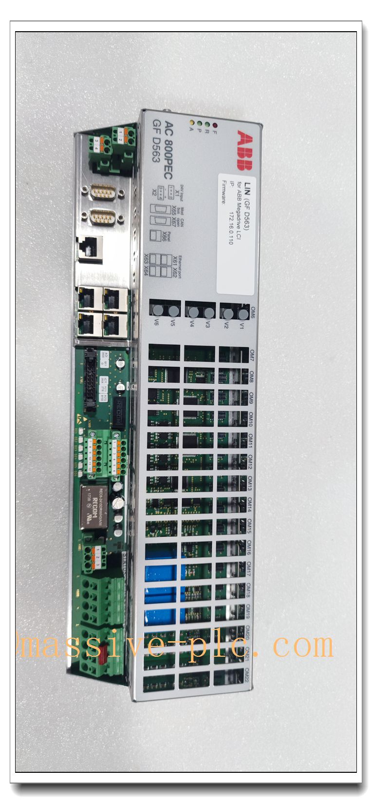
Description
GFD563A101 (3BHE046836R0101) Product Technical Manual
Product Core Introduction
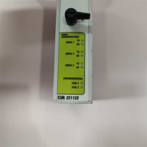
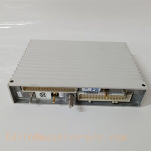
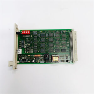
The GFD563A101, part number 3BHE046836R0101, is ABB high-speed processor control unit belonging to AC 800PEC series under 800xA platform, specially developed for power electronics and generator excitation control (Unitrol 5000 / Unitrol 6000 excitation systems). Equipped with CPU+FPGA dual-core architecture, it delivers ultra-fast real-time control cycle down to 100μs for excitation regulation, voltage control, reactive power adjustment and thyristor firing pulse calculation. It handles high-speed closed-loop algorithm, I/O data acquisition, fault diagnosis and multi-protocol communication with upper HMI and engineering stations. Widely used as critical spare for hydro/thermal power generator excitation cabinets, static var compensator SVG and high-speed power conversion control racks. Redundant hot-standby configuration is supported for non-interrupt power plant operation.
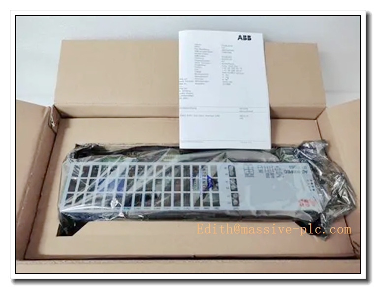
GFD563A101 3BHE046836R0101
Main Technical Specifications
- Model: GFD563A101, Order Code: 3BHE046836R0101
- Power Supply: 24VDC, operating range 18–30VDC
- Power Consumption: Max 18W
- Control Core: Industrial CPU + FPGA co-processor
- Fastest Control Cycle: 100 μs
- Onboard Memory: 128MB RAM, 64MB non-volatile Flash
- Communication Interfaces: Dual 10/100Mbps Ethernet, S800 ModuleBus, CEX bus, PROFIBUS
- Supported Protocols: Modbus TCP, Modbus RTU, PROFIBUS DP, ABB proprietary bus
- Operating Temperature: 0°C ~ +60°C
- Storage Temperature: -40°C ~ +85°C
- Relative Humidity: 5%–95% RH, non-condensing
- Protection Class: IP20 (cabinet rack slot installation only)
- MTBF: ≥105,000 hours
- Mounting: Standard ABB rack plug-in slot mounting
- Net Weight: 1.62 kg
- Status Indicators: Power, Run, Master/Standby, Fault, Network A/B, FPGA Status LED indicators
Recommended Homologous Series Models
- GFD563A102: Updated hardware revision of GFD563A101, improved EMC and component longevity, form-fit-function compatible replacement.
- GFD550A01: Entry high-speed controller for small excitation and power conversion applications, lower cost.
- GFD564A101: Expanded high-performance variant with extra high-speed pulse output channels for multi-bridge thyristor control.
- 3BHE046837R0101: Matching I/O terminal board paired with GFD563A101 for field signal conditioning.
Professional Quality Control & Test Standard Operating Procedures (SOP)
4.1 General Test Standard
All GFD563A101 units are inspected complying with ISO9001, IEC61131 and IEC61000 EMC standards. Each unit has unique serial number for full lifecycle traceability.
4.2 Core Test SOP
- Visual & Mechanical Inspection: Inspect front panel, PCB, backplane edge connector, terminal and network ports for scratches, cracks, solder defects and bent pins; verify rack slot mechanical fit against engineering drawings.
- Power-On Basic Function Test: Apply minimum, rated and maximum 24VDC supply; validate power, run and fault LED behaviour; check no overcurrent, short-circuit or boot failure.
- BIST Hardware Self-Test: Execute built-in self-test to verify RAM, flash memory, FPGA and peripheral circuits; load excitation control algorithm to validate real-time calculation performance.
- Redundancy Switchover Test: Install two identical cards as master/standby pair in test rack; trigger manual and automatic bumpless switchover, verify excitation control loop maintains stable output without disturbance.
- Communication & Bus Test: Connect to S800 I/O modules, HMI and engineering workstation; test Ethernet, PROFIBUS and ModuleBus; monitor packet loss and bus error counters under full algorithm load.
- EMC Immunity Test: ESD, EFT, surge and radiated interference test following IEC61000; ensure no algorithm crash, pulse distortion or false fault alarms.
- Temperature Cycling Test: 0°C ↔ +60°C thermal cycling for 40 cycles, 2 hours per cycle; validate FPGA high-speed calculation stability and memory read/write reliability.
- Vibration & Shock Test: 10–150Hz sinusoidal vibration and mechanical shock test to verify solder joint and connector robustness for power plant cabinet vibration environment.
- Continuous Burn-In Aging: 160 hours burn-in at 55°C running full excitation control algorithm; monitor temperature rise and real-time control accuracy to screen intermittent hidden faults.
- Final Inspection & Packaging: Reset factory parameters, record serial number, anti-static sealing with inspection certificate attached.
New Module Installation Guidelines
5.1 Pre-installation Preparation
Cut off rack backplane and excitation cabinet power; confirm model and part number match purchase order; inspect anti-static packaging and connector integrity. Wear anti-static wristband before touching PCB. Prepare screwdriver, torque screwdriver and engineering workstation for firmware download and parameter commissioning.
5.2 Installation Steps
- Open target rack slot cover; align with rack guide rails.
- Slide module fully into slot until backplane connector is securely engaged.
- Tighten front panel retaining screws to specified torque to prevent loosening under power plant vibration.
- For redundant excitation configuration, install second identical into adjacent paired slot.
- Connect Ethernet and PROFIBUS communication cables; separate control signal cables from high-power thyristor power cables to minimize EMI.
- Wire 24VDC power terminals, confirm polarity correct and no bare copper exposure.
5.3 Post-installation Commissioning
Restore rack power and power up the control unit; observe LED indicators to confirm normal power and boot status. Download matching firmware and excitation control application via engineering tool; configure network address, redundancy parameters and thyristor pulse parameters. Perform manual master/standby switchover test multiple times, verify generator voltage and excitation current remain stable during switchover. Run continuous 60-minute stability test; check high-speed pulse output and communication before putting online.
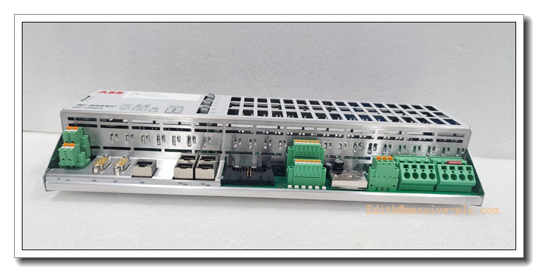
GFD563A101 3BHE046836R0101
Application Scenarios & Product Features
6.1 Core Application Scenarios
- Thermal & hydro power generator Unitrol 5000/6000 static excitation control systems
- SVG / STATCOM reactive power compensation and power electronic control racks
- Power plant generator voltage regulation, reactive power control and excitation interlock protection
- Metallurgy high-power rectifier and rolling mill power conversion control
- Legacy ABB AC800PEC excitation system spare replacement and cabinet retrofit
6.2 Core Product Features
- CPU+FPGA co-processing architecture, ultra-fast 100μs real-time control cycle for power electronics
- Designed for ABB Unitrol generator excitation systems, implements thyristor firing algorithm and closed-loop voltage regulation
- Supports hot standby redundant configuration with bumpless master/standby switchover
- Multi-channel communication ports, compatible with 800xA DCS, HMI and S800 I/O system
- Built-in comprehensive hardware self-diagnosis, real-time fault LED and diagnostic data upload
- High-grade EMC protection, stable operation under strong electromagnetic interference in power plant excitation cabinets
- Rack plug-in design, convenient spare replacement and maintenance
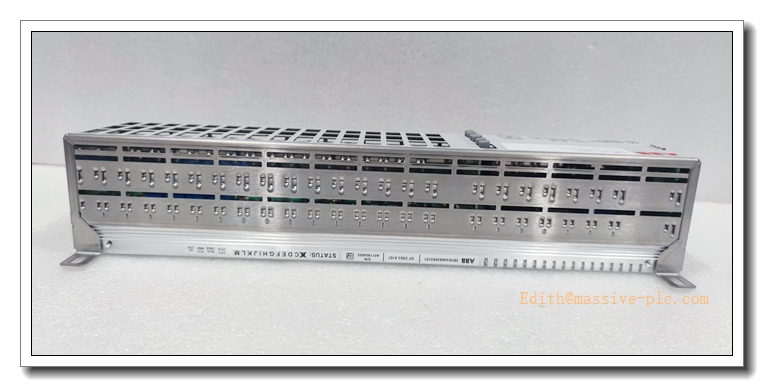
GFD563A101 3BHE046836R0101
Frequently Asked Questions (FAQ)
Q1: Power LED remains off after rack installation A1: Verify rack 24VDC supply voltage and polarity; inspect loose backplane contact or damaged wiring; measure terminal voltage. If input voltage normal while LED stays off, replace the control unit.
Q2: Fault LED flashes continuously after power on A2: Re-seat module and retighten front screws; inspect backplane connector for oxidation or contamination; verify firmware version compatibility. Re-download valid firmware and excitation application program if required.
Q3: Redundancy switchover causes generator voltage fluctuation A3: Confirm both master and standby cards run identical firmware and excitation algorithm; check redundancy synchronization bus connection; adjust synchronization parameters via engineering software.
Q4: Thyristor firing pulse loss or distortion A4: Check optical pulse cable connection and integrity; inspect cabinet high-frequency EMI interference; verify FPGA status and pulse configuration parameters.
Q5: Intermittent communication dropout with upper 800xA system A5: Inspect Ethernet cable shielding and grounding; check network switch and bus load; separate network cables away from high-current power cables.
A6: Yes. It can operate as standalone controller for non-critical excitation or power conversion racks. Redundant pairing is mandatory for large generator main excitation loops requiring uninterrupted control.


 Start Chat




