Description
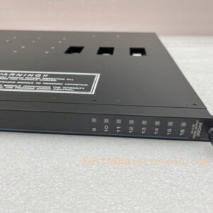
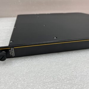
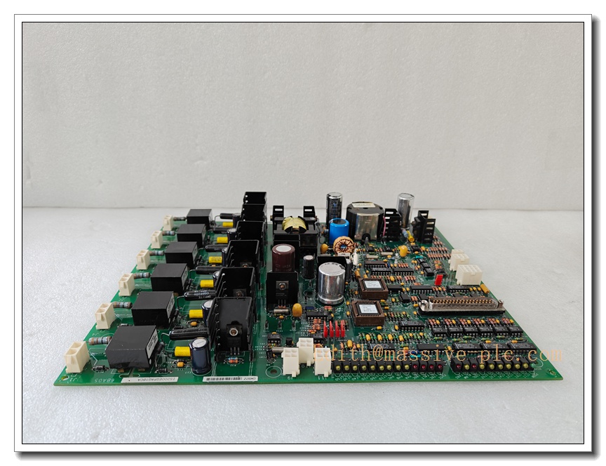
GE IS200EGPAG1BEC Exciter Gate Pulse Amplifier (EGPA) Board for EX2100 / Mark VI Speedtronic Turbine Excitation Control System
Product Overview
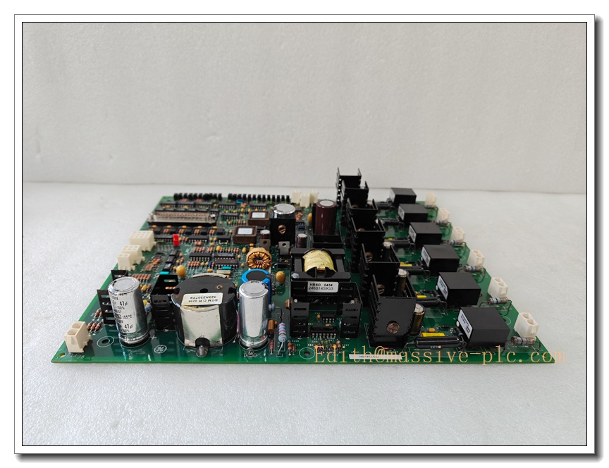
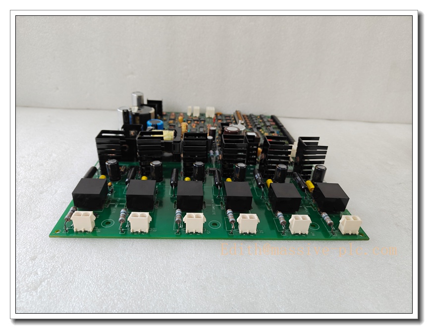
The GE IS200EGPAG1BEC (EGPA) is an enhanced gate pulse amplifier PCB designed for GE EX2100 generator excitation control systems under the Mark VI Speedtronic turbine control platform. It receives low-level TTL firing commands from the ESEL (Excitation System Equipment List) controller board, amplifies the signals into high-current gate pulses to trigger six SCR thyristors within the power rectifier bridge. This board performs real-time monitoring of SCR conduction status, heat sink temperature and bridge airflow, while implementing fast protective fault detection for open gate, short circuit and over-temperature conditions. The suffix “BEC” denotes enhanced monitoring circuitry and revised hardware artwork; it is backward pin-compatible with the base IS200EGPAG1B variant. This legacy board is no longer actively produced by GE and is supplied mainly as spare replacement for existing power plant excitation cabinets.
GE IS200EGPAG1BEC
Key Technical Specifications
- Part Number: IS200EGPAG1BEC
- Manufacturer: General Electric (GE)
- Product Type: Exciter Gate Pulse Amplifier (EGPA)
- Compatible System: EX2100 / EX2100e, Mark VI Speedtronic Turbine Control
- Gate Output: 6 firing pulse channels for SCR rectifier bridge
- Peak Gate Current: 2 A per channel
- Open-circuit Gate Voltage: 15 VDC
- Input Command: 5 V TTL logic signals from ESEL board
- Logic Power Supply: 24 VDC ±15%
- Isolation Rating: 2500 Vrms
- Onboard Diagnostics: Gate open detection, desaturation short-circuit protection, temperature / airflow monitoring, fault relay output
- Indicators: On-board red/green LED status indicators
- Connectors: Dual 50-pin D-sub connectors + terminal block for monitoring signals
- Operating Temperature: 0°C ~ +60°C
- Storage Temperature: -40°C ~ +85°C
- Relative Humidity: 5% to 95% non-condensing
- Mechanical: Multi-layer coated PCB, rack slot mount
- Dimensions (W×H×D): 190 × 110 × 30 mm
- Weight: ~0.35 kg
Recommended 8 Similar Series Models (Mark VI / EX2100 family)
- GE IS200EGPAG1B (base version, direct hardware compatible)
- GE IS200ESELH1A ESEL Excitation Control Board
- GE IS200GPAAG1A Gate Pulse Amplifier
- GE IS200TREGH1A Regulator Board for EX2100
- GE IS200ERIOH1B Excitation I/O Board
- GE IS200STCIH2A Contact Input Terminal Board
- GE IS200FCTAH1A Field Current Transducer Board
- GE IS200DSPX1H Digital Signal Processor Board (Mark VI)
Quality Control & Test Standard Operating Procedure (SOP)
- Visual Inspection: Inspect coated PCB, solder joints, capacitors, D-sub connectors, terminal block and printed part marking. Confirm part revision, check for burn marks, corrosion, cracked traces or connector pin damage.
- Continuity & Isolation Test: Perform pin continuity check for gate output and logic power pins; hipot isolation test to verify 2500 Vrms isolation between low-voltage logic side and high power gate outputs.
- Power-Up Functional Test: Apply 24 VDC logic power gradually. Check quiescent current, LED boot sequence, no overheating or abnormal component noise.
- Built-in Diagnostic Test: Trigger internal self-test; verify gate channel open/short fault detection and fault relay switching function.
- Gate Pulse Output Test: Inject TTL firing command signals from signal generator. Validate 6-channel pulse timing, peak current and voltage waveform for each SCR gate output.
- Monitoring Input Simulation: Simulate heat sink temperature and airflow sensor signals, confirm correct analogue measurement and alarm threshold response.
- Backplane / ESEL Interface Test: Interface with ESEL controller board. Verify reliable command reception and fault status feedback to the main EX2100 regulator.
- Environmental Burn-in Test: Run continuous powered burn-in at rated operating temperature to screen early failure components.
- Final Recheck & Documentation: Repeat pulse output and diagnostic tests after burn-in. Generate serial-number traceable test report before anti-static packaging.
New Module Installation Guide
- Pre-Install Preparation: Perform LOTO lockout-tagout procedure on excitation cabinet and high-voltage rectifier section. Wear ESD wrist strap and anti-static mat. Confirm part number and hardware revision match site BOM.
- Rack Slot Inspection: Inspect backplane and D-sub mating connectors for bent pins, dust or oxidation. Clean slot guide rails.
- PCB Insertion: Align the EGPA board into the Mark VI rack slot. Slide fully home until D-sub connectors mate completely. Tighten front retaining screws evenly.
- Wiring Termination: Connect 24 VDC logic supply, ESEL command cable, SCR gate outputs and temperature/airflow monitoring wiring per wiring schematic. Separate high-power pulse cables from low-level control cables and implement proper shielding.
- Power Restore: Energize low-voltage 24VDC logic power only (keep high power bridge de-energized). Check front board LEDs and confirm no active hardware faults.
- Commissioning & Channel Test: Use engineering tool to run excitation system self-test. Execute simulated firing sequence to verify all six gate pulses output correctly, validate fault detection response.
- Dry Run & System Integration: Perform full system dry run without generator field excitation. Confirm fault alarms and relay status report back to Mark VI HMI.
- Post-Installation Documentation: Save system configuration, record board serial number and commissioning test data in plant maintenance log.
Application Scenarios & Features
Application Scenarios
- Generator / EX2100e excitation control cabinets for steam and gas turbine power plants
- Heavy-duty synchronous generator excitation rectifier SCR bridge firing control
- Combined-cycle power generation turbine control systems with Mark VI Speedtronic platform
- Retrofit and spare replacement of legacy GE excitation control panels
- Hydro generator excitation protection and pulse drive systems
Core Features
- 6-channel high-current SCR gate pulse amplification for excitation rectifier bridge
- Converts low-voltage TTL control signals from ESEL board to high energy firing pulses
- Fast fault detection for gate open, short circuit and SCR desaturation protection
- Integrated temperature and airflow monitoring for power bridge thermal protection
- Isolated high-voltage gate outputs to protect turbine control logic circuits
- Onboard fault relay to feed failure status back to regulator
- Conformal coated PCB for dust, moisture and chemical resistance in cabinet environments
- Seamless integration within GE Mark VI Speedtronic turbine and excitation ecosystem
GE IS200EGPAG1BEC
FAQ
Q1: What is the difference between IS200EGPAG1B and IS200EGPAG1BEC?
A1: IS200EGPAG1BEC is enhanced revision of the base IS200EGPAG1B. It adds improved temperature/airflow sampling, stronger EMI filtering and enhanced SCR conduction validation. Pinout and mechanical footprint are identical, allowing direct drop-in replacement without rewiring or program modification.
Q2: Can I install this board while excitation cabinet remains energized?
A2: Not recommended. Although Mark VI rack supports module removal, this board directly drives SCR firing pulses. De-energize both high-power rectifier and 24VDC logic supply and apply LOTO before replacement.
Q3: What will happen if EGPA board detects gate open fault?
A3: The board triggers fault relay, sends fault signal to ESEL/ regulator. The excitation system will raise alarm and may initiate excitation trip depending on system configuration.
Q4: Is this board SIL certified?
A4: SIL assessment applies to the complete excitation and turbine protection system, not the standalone EGPA PCB. Full system safety evaluation is required to achieve SIL compliance.
Q5: What sensors connect to the monitoring terminals of EGPA?
A5: Heat sink temperature RTD/thermistor and airflow differential pressure sensors for SCR power bridge health monitoring.
Q6: Can mismatched ESEL and EGPA firmware cause firing malfunction?
A6: Yes. Always verify firmware compatibility between ESEL controller and IS200EGPAG1BEC before replacement. Mismatched firmware can lead to missing pulses or incorrect fault reporting.
Q7: What maintenance and calibration interval is recommended?
A7: Annual visual inspection and functional pulse test; full bench calibration every 24 months, subject to plant maintenance and grid requirements.
Q8: Is still in production?
A8: GE has discontinued this legacy Mark VI board. Only refurbished or new-old-stock spare parts are available for existing plant maintenance. New excitation projects use modern GE control platforms.