
Description
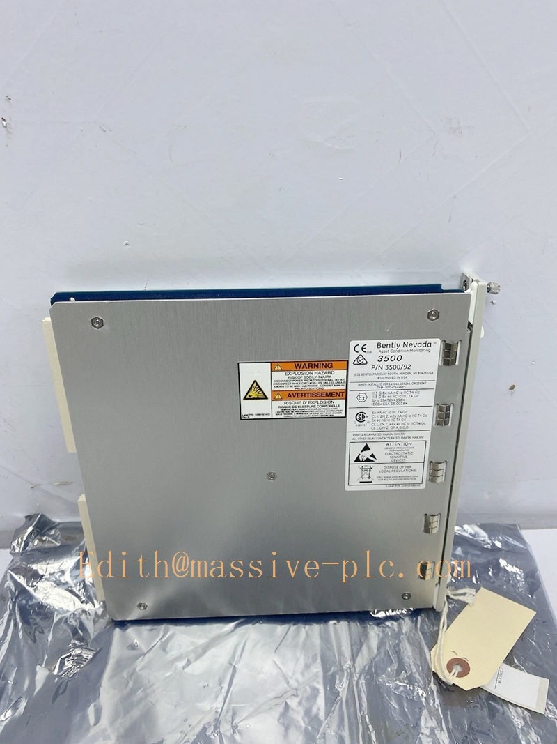
Bently‑Nevada 3500/92‑04‑01‑00 Communication Gateway Assembly (136180‑01 +136188‑02)
Product Description
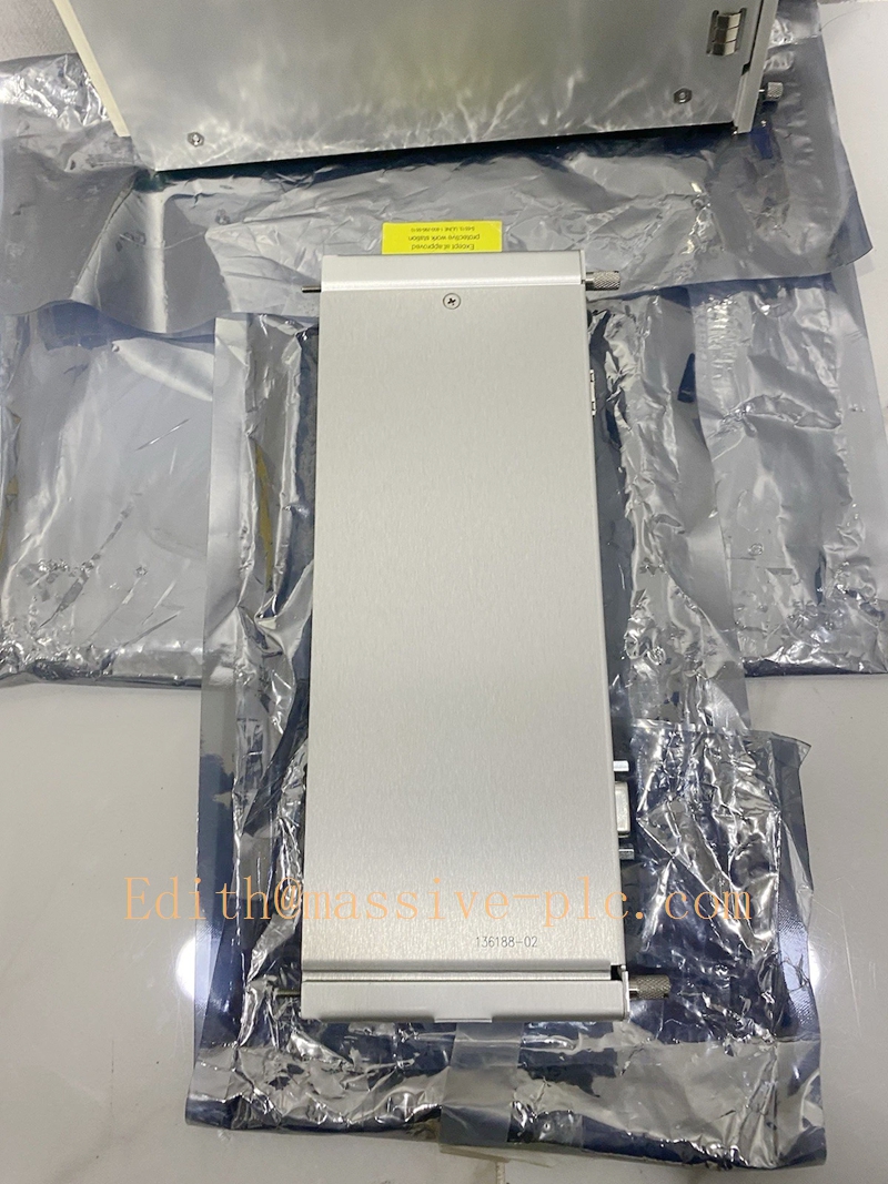
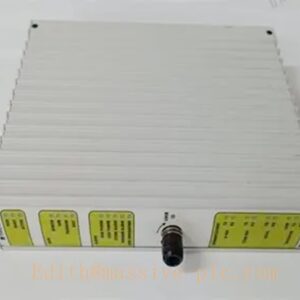
The 3500/92‑04‑01‑00 is a full‑height communication gateway module for Bently‑Nevada 3500‑series machinery‑protection rack. The assembly consists of front processor main board 136180‑01 and rear mixed‑interface I/O board 136188‑02.
This gateway bridges the 3500 rack backplane bus to external plant automation systems. It collects real‑time measured values, alarm status, and diagnostic data from all monitor modules within the rack, and exports these data via Ethernet and RS‑485 serial interfaces. It supports Modbus‑TCP, Modbus‑RTU and proprietary Bently‑Nevada host protocol for connection to DCS, PLC, SCADA and configuration software.
Multiple 3500/92 modules may be installed in one rack for redundant communication or multi‑host access. Important: Gateway faults or communication loss will not affect local machinery‑protection trip logic; protection functions run independently on monitor modules. OEM production discontinued; available only as aftermarket replacement spare for legacy turbomachinery TSI racks。
Order code breakdown:3500/92‑04‑01‑00‑04:Rear I/O = Ethernet + RS‑485 Modbus mixed‑interface board‑01:Memory configuration = Low‑memory version‑00:No third‑party agency certification
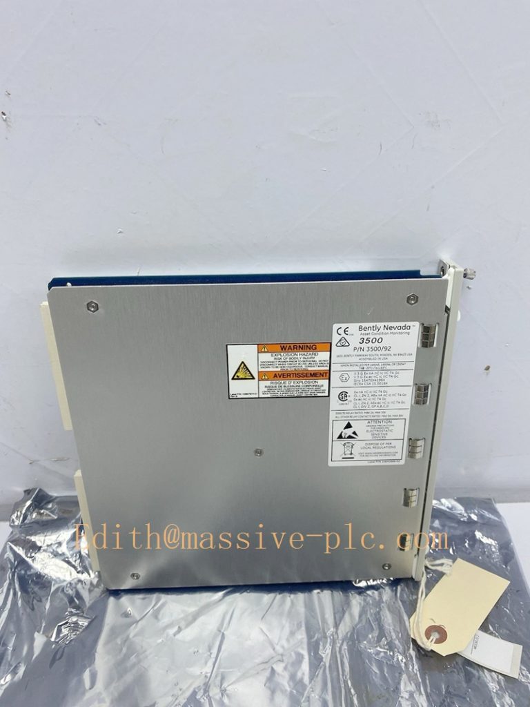
136180-01
Technical Specifications
| Item | Specification |
|---|---|
| Complete Assembly PN | 3500/92‑04‑01‑00 (136180‑01 +136188‑02) |
| Front Main Processor Board | 136180‑01 Gateway CPU board |
| Rear I/O Daughter‑Board | 136188‑02, 10BASE‑TX RJ45 Ethernet + RS‑485 serial port |
| Form Factor | Full‑height module, occupies one full‑height rack slot |
| Ethernet Interface | 10BASE‑TX, RJ45 connector |
| Serial Interface | RS‑485, 9‑pin D‑SUB connector, supports half‑duplex / full‑duplex |
| Supported Protocols | Modbus‑TCP (Ethernet), Modbus‑RTU (RS‑485), Bently‑Nevada proprietary protocol |
| Modbus Function | User‑configurable Modbus register mapping utility |
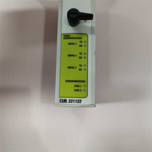
| Front‑panel Indicator | Module OK LED, Ethernet activity LED, serial communication status LED |
| Typical Power Consumption | 5.6 W, powered by rack backplane bus |
| Hot‑swap Rule | Rear I/O board supports hot‑swap under rack powered‑on; front main‑board requires slot power‑off |
| Operating Temperature | ‑30 °C ~ +65 °C (‑22 °F ~ +149 °F) |
| Storage Temperature | ‑40 °C ~ +85 °C (‑40 °F ~ +185 °F) |
| Relative Humidity | 5‑95 % RH, non‑condensing |
| Dimension(H×W×D) | 241.3 mm ×24.4 mm ×241.8 mm (9.50 in ×0.96 in ×9.52 in) |
| Approximate Total Weight | 0.82 kg |
| Product Status | Discontinued OEM production, aftermarket spare‑part only |
Variant note‑01:Rear I/O Ethernet+RS232/RS422‑02:Rear I/O RS485 only‑03:Rear I/O Ethernet+RS232‑04:Rear I/O Ethernet+RS485 (this model)Baker Hugh…
Key Features & Benefits
- Dual‑media communication interface: Equipped with both 10M Ethernet and RS‑485 serial port, supports simultaneous connection to network‑based DCS and serial‑based PLC systems, flexible for diverse plant‑system architectures.
- Multi‑protocol industrial integration: Supports Modbus‑TCP / Modbus‑RTU standard protocols, enables 3500 rack vibration, temperature, speed and alarm data accessible to mainstream process‑control platforms without extra conversion hardware.
- Configurable Modbus register mapping: Users can assign required measurement points to Modbus registers, filter unused parameters, optimise data‑reading efficiency for host‑side system.
- No interference with protection safety: Gateway operates as a read‑only data export device. Module failure or communication disconnect will not influence monitor alarm and trip outputs, maintains machinery‑protection integrity.
- Multi‑module expandability: Multiple 3500/92 gateways can co‑exist in single rack, realises redundant communication paths or multi‑host parallel‑access requirement.
- Backward‑compatible maintainable architecture: Compatible with full 3500 series rack hardware, works together with 3500/22‑TDI, 3500/15 redundant power, all 3500 monitor and relay modules. Rear‑side I/O board supports online hot‑swap for maintenance.
Application Fields
‑ Power‑generation, petrochemical and natural‑gas facilities: data‑communication gateway for 3500 machinery‑protection racks monitoring steam‑turbine, gas‑turbine, centrifugal‑compressor and reciprocating‑compressor assets. Transfers vibration, thrust, temperature, speed and alarm status to DCS, PLC and plant SCADA via Modbus protocols.‑ Industrial rotating‑machinery projects requiring Modbus‑TCP / Modbus‑RTU digital data interface between 3500 TSI and process‑control system.‑ Spare‑part replacement and system retrofit for legacy 3500 racks originally equipped with 3500/92‑04‑01‑00 Ethernet+RS485 communication‑gateway assembly.
Related Recommended Products
‑ 3500/05 series: 3500‑system rack chassis‑ 3500/15 series: Redundant rack power‑supply modules‑ 3500/22 / 3500/22M TDI: Rack transient‑data‑interface gateway‑ 3500 monitor family: 3500/40M, 3500/42M, 3500/50, 3500/60 etc., data source modules‑ 3500 Rack Configuration Software: Tool for gateway network setting, Modbus register mapping configuration‑ DCS / PLC host system: Modbus master device for reading 3500/92 gateway data
Installation and Maintenance
Installation
- Assemble front gateway main‑board 136180‑01 and matched rear‑I/O board 136188‑02 as a complete unit; insert assembly into any available full‑height slot inside 3500 rack.
- Connect RJ45 Ethernet cable and RS‑485 serial cable to rear‑board interfaces, follow RS‑485 bus termination specification for multi‑drop serial network.
- Connect configuration laptop, launch 3500 Rack Configuration Software; set IP address, serial baud‑rate, parity, and configure Modbus register mapping table, download configuration to rack.
- Power‑up rack; verify front‑panel OK‑LED keeps illuminated; check rack event‑log for gateway hardware or backplane‑communication faults; establish connection with Modbus master host and validate data reading.
Important Note: Only rear‑side I/O board supports hot‑swap when rack powered‑on. Front main‑board must be removed after corresponding slot power disabled. Gateway cannot modify monitor protection setpoints; protection parameters are configured on each monitor module.
Maintenance
- Periodically inspect rear‑side RJ45 and D‑SUB connectors, front‑panel LED status during site routine inspection.
- Regularly download rack event‑log to review gateway communication errors and hardware‑fault records.
- When rear‑I/O circuit fault occurs, perform hot‑swap for rear termination board under rack powered‑on condition, verify Ethernet & serial communication function after replacement.
- When front‑processor‑board hardware fault occurs, cut off slot power before replacing front board; reassemble with matched rear I/O module, re‑download rack configuration and validate full‑function recovery.
- Avoid mechanical shock and conductive contamination during module‑handling. Refer to Bently‑Nevada official document Doc‑141542 (3500/92 Communication Gateway Datasheet & Operation Manual) for complete installation constraints and detailed troubleshooting guidance.


 Start Chat




