
Description
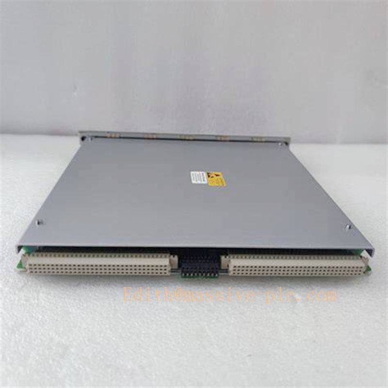
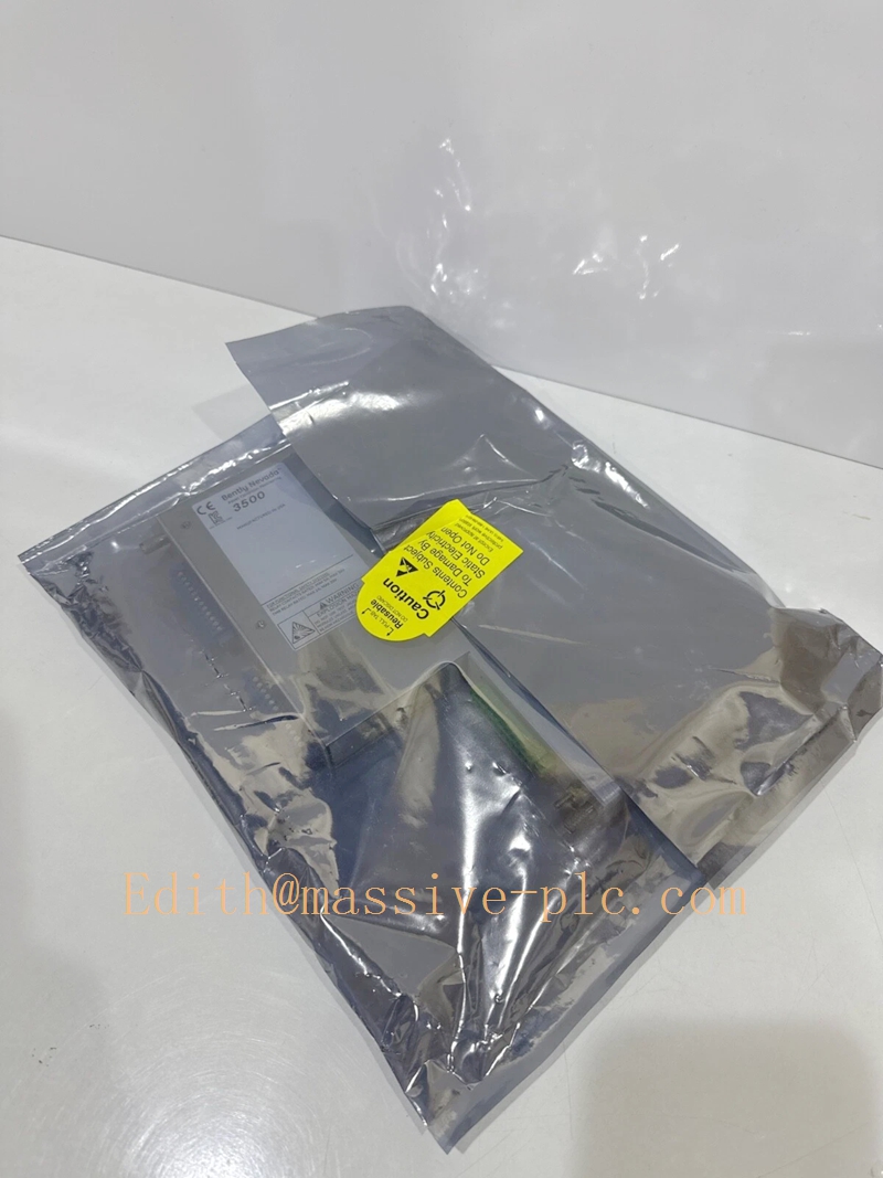
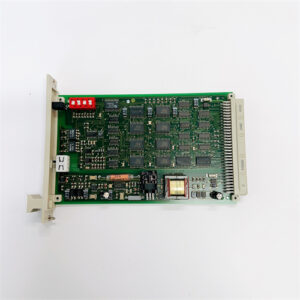
Bently‑Nevada 3500/70M‑05‑00 Reciprocating Impulse / Velocity Monitor Assembly (176449‑09 Main Board + 135489‑03 Rear I/O Module)
Product Description
The 3500/70M‑05‑00 is a full‑height four‑channel seismic monitoring module designed for Bently‑Nevada 3500‑M‑series machinery‑protection rack, specifically optimized for reciprocating machinery protection. The complete assembly consists of front signal‑processing main board 176449‑09 and rear internal‑termination I/O daughter‑board 135489‑03.
This monitor accepts input signals from seismic accelerometer / velocity transducers installed on reciprocating compressors. Each channel can be software‑configured for impulse acceleration, acceleration‑2, reciprocating velocity or low‑frequency reciprocating velocity measurement. It compares real‑time measured values against user‑programmed Alert and Danger alarm thresholds, publishes vibration amplitude, impulse data and alarm status over rack backplane bus to relay modules, TDI gateway and System 1® condition‑monitoring software.
3500/70M‑05‑00 complies with API‑670 standard for machinery protection. It cannot operate standalone; it relies on rack backplane power and 3500/22 TDI for configuration download and event logging. OEM production discontinued; available only as aftermarket replacement spare for legacy reciprocating‑compressor TSI systems.
Technical Specifications
| Item | Specification |
|---|---|
| Complete Assembly PN | 3500/70M‑05‑00 (176449‑09 +135489‑03) |
| Front Main Processor Board | 176449‑09 (4‑channel reciprocating impulse‑velocity CPU board) |
| Rear I/O Daughter‑Board | 135489‑03 (internal screw‑terminal termination, seismic sensor interface) |
| Form Factor | Full‑height module, occupies one full‑height rack slot |
| Channel Quantity | 4 independent input channels, grouped in two channel‑pairs |
| Supported Transducers | Seismic accelerometer, velocity transducer for reciprocating equipment |
| Measurement Modes | Impulse Acceleration, Acceleration‑2, Reciprocating Velocity, Low‑Frequency Reciprocating Velocity |
| Input Impedance | 20 kΩ typical per channel |
| Alarm Configuration | Per‑channel Alert / Danger thresholds, configurable alarm delay & latch function |
| Front‑panel Indicator | OK LED, per‑channel alarm & sensor‑fault LED indicators |
| Typical Power Consumption | 10 W |
| Operating Temperature | ‑30 °C ~ +65 °C (‑22 °F ~ +149 °F) |
| Storage Temperature | ‑40 °C ~ +85 °C (‑40 °F ~ +185 °F) |
| Relative Humidity | 5‑95 % RH, non‑condensing |
| Dimension(H×W×D) | 241 mm × 24.4 mm × 242 mm (9.50 in × 0.96 in × 9.52 in) |
| Approximate Total Weight | 0.91 kg (2.0 lbs) |
| Certification | CE, UL, CSA marked |
| Product Status | Discontinued OEM production, aftermarket spare‑part only |
Key Features & Benefits
- Reciprocating‑machinery dedicated measurement algorithm: Optimized for crosshead vibration, crankcase impulse and valve impact monitoring on reciprocating compressors, captures impulse shock characteristics which general rotating‑machinery monitors cannot effectively processBaker Hugh….
- Flexible multi‑mode channel configuration: Each channel‑pair supports independent function assignment; mixed measurement modes can run within one single module, improving channel‑utilization for multi‑point reciprocating‑equipment monitoring.
- Internal field‑termination design: Field seismic‑transducer cables land directly onto screw terminals of rear‑side 135489‑03 module, eliminating extra external terminal blocks and simplifying cabinet wiring layout.
- Comprehensive sensor self‑diagnosis: Detects transducer open‑circuit, short‑circuit and abnormal signal conditions; fault events are time‑stamped and stored in rack event‑log, with front‑panel LED local indication for fast on‑site troubleshooting.
- TMR‑system compatible: Supports triple‑modular‑redundant protection deployment when three identical 3500/70M modules are grouped, satisfying high‑safety reciprocating‑compressor interlock‑trip requirements.
- Backward‑compatible maintainable architecture: Fully compatible with all 3500‑M‑series monitors, TDI gateway and legacy firmware. Rear‑side 135489‑03 I/O supports hot‑swap under rack powered‑on; front‑side 176449‑09 main‑board requires slot power‑down before removal.
Application Fields
- Petrochemical and natural‑gas processing plants: monitors crosshead vibration, crankcase shock impulse and valve‑impact vibration for large reciprocating compressors within 3500‑M TSI racks, implements machinery‑protection alarm and trip interlock according to API‑670 specificationBaker Hugh….
- Reciprocating‑equipment condition‑monitoring projects requiring seismic impulse / velocity acquisition, local alarm indication and trending‑data uploading to System 1® diagnostic platform.
- Spare‑part replacement and system retrofit for legacy 3500 racks originally equipped with internal‑termination variant 3500/70M‑05‑00 reciprocating‑impulse‑velocity monitor assembly.
Related Recommended Products
- 3500/22‑01‑01‑00 (TDI): Rack‑level gateway for configuration download, event‑log reading and vibration‑data uploading to System 1® software
- 3500/15 series: Rack power‑supply modules
- 3500/32‑01‑00 / 3500/34‑00‑00: Relay‑output modules for vibration‑triggered alarm and trip interlock
- 3500 Rack Configuration Software: Parameter‑setup tool for measurement‑mode selection, range setting and alarm‑threshold configuration
Installation and Maintenance
Installation
- Mate front main‑board 176449‑09 firmly with rear‑side 135489‑03 I/O module; insert full‑height assembly into any available full‑height slot of the 3500 rack.
- Wire seismic transducer field cables onto screw terminals of 135489‑03 rear module, strictly follow seismic‑sensor wiring specifications and shield‑grounding requirements.
- Launch 3500 Rack Configuration Software; define each channel‑pair measurement mode, measurement range, Alert/Danger alarm thresholds and alarm‑delay parameters; download configuration to rack.
- Power‑up rack; confirm front‑panel OK‑LED is illuminated; inspect rack event‑log for channel open‑circuit / short‑circuit fault diagnostics; verify stable vibration‑impulse reading for each sensor channel.
Important Note: Only rear‑side 135489‑03 supports hot‑swap. Front‑side 176449‑09 main‑board must be installed or removed with corresponding slot power disabled.
Maintenance
- Periodically inspect rear‑module screw terminals and connectors for dust accumulation, corrosion and loose wiring connections.
- Regularly review rack event‑log for monitor‑channel fault and transducer‑failure alarms.
- For rear‑I/O circuit fault: hot‑swap 135489‑03 while rack remains powered‑on, verify each‑channel measurement function after replacement.
- For main‑board logic fault: power‑down assigned full‑height slot before extracting 176449‑09 main‑board; reassemble with matched rear I/O module, download rack configuration and validate full‑function recovery.
- Avoid mechanical shock and conductive contamination during module‑handling. Refer to Bently‑Nevada official document Doc‑141544 (3500/70M Datasheet & Manual) for complete installation constraints and detailed troubleshooting guidance.


 Start Chat




