
Description
Bently‑Nevada 3500/46M (176449‑06) Hydro Monitor
Product Description
The 176449‑06 is the front main processing board for the Bently‑Nevada 3500/46M Hydro Monitor, a dedicated 4‑channel monitor specially engineered for hydro‑turbine generator protection within the 3500 machinery‑protection rack system. It mates with matched rear I/O termination board to complete a full monitor assembly.
This module acquires signals from proximity probes, air‑gap sensors, seismic transducers and dynamic pressure sensors. Channels are configured in pairs, supporting multiple hydro‑specific measurement modes including hydro radial vibration, air‑gap, thrust position, stator‑end‑winding vibration, velocity, acceleration and multimode measurement functions. It executes on‑board alarm comparison for Alert / Danger set‑points, delivers machinery protection and predictive maintenance data. Protection logic runs locally on hardware; monitoring and alarm functions keep working even when host‑software communication fails. OEM production discontinued; supplied as aftermarket spare part for legacy hydro‑power plant TSI systems. Country of Origin: USA.
Part Number Breakdown‑176449‑06:Front CPU processing board for 3500/46M Hydro Monitor‑Matching rear I/O board:selectable internal screw‑terminal or external‑termination rear module‑Complete assembly model:3500/46M‑XX‑XX‑00‑No third‑party safety‑agency certification
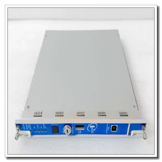
Bently Nevada 350046M 176449-06
Technical Specifications
| Item | Specification |
|---|---|
| Part Number | 176449‑06 |
| Product Type | Front processing board for 3500/46M Hydro Monitor |
| Channel Quantity | 4 input channels, configured by channel‑pairs (Ch1‑2, Ch3‑4) |
| Supported Sensors | Proximity probe, air‑gap sensor, velocity transducer, accelerometer, dynamic pressure transducerBaker Hugh… |
| Measurement Functions | Hydro Radial Vibration, Hydro Air Gap, Hydro Thrust, Hydro Velocity, Hydro Acceleration, Multimode series functions, Hydro Stator End Winding (SEW) |
| Transducer Excitation | ‑24 VDC sensor power supply |
| Buffered Output | Coaxial buffered transducer output per channel, short‑circuit protected |
| Recorder Output | 4‑20 mA analog recorder output per channel |
| Typical Power Consumption | 7.8 W, powered by 3500 rack backplane bus |
| Front‑panel Indicators | Module OK LED, Bypass LED, per‑channel alarm LED indicators |
| Hot‑swap Rule | Rear I/O board supports hot‑swap under rack powered‑on; front 176449‑06 board requires slot power‑off before removal |
| Dimension(H×W×D) | 241.3 mm ×24.4 mm ×99.1 mm (9.50 in ×0.96 in ×3.90 in) |
| Operating Temperature | ‑30 °C ~ +65 °C (‑22 °F ~ +149 °F) |
| Storage Temperature | ‑40 °C ~ +85 °C (‑40 °F ~ +185 °F) |
| Relative Humidity | 5‑95 % RH, non‑condensing |
| Product Status | Discontinued OEM production, aftermarket spare‑part only |
Variant note‑3500/46M is dedicated hydro‑turbine monitor; do not confuse with general‑purpose 3500/42M monitor. Multiple rear I/O variants available for different field‑wiring schemes.
Key Features & Benefits
- Hydro‑turbine‑oriented multi‑measurement capability: Optimized for hydro‑generator characteristics, covers shaft radial vibration, rotor‑stator air gap, thrust position, stator‑end‑winding vibration and casing seismic parameters within one single slot, reducing rack‑slot occupation for hydro‑unit monitoring.
- Channel‑pair flexible configuration: Two channel‑pairs can run different measurement functions simultaneously, adapts to mixed‑sensor signal acquisition requirements of hydro‑turbine units.
- Independent on‑board protection logic: Threshold comparison and alarm judgment execute on local hardware. Loss of TDI‑to‑host communication cannot disable machinery‑protection functions, guarantees protection integrity for critical hydro‑power assets.
- Abundant signal output interfaces: Buffered coaxial outputs for portable analysis instruments; per‑channel 4‑20 mA recorder outputs for connecting recorders or DCS acquisition channels.
- Comprehensive self‑diagnosis mechanism: Continuously detects sensor open‑circuit, short‑circuit and module hardware faults. All fault events are time‑stamped and stored into rack event‑log for rapid troubleshooting.
- Full backward compatibility with 3500 ecosystem: Cooperates with 3500/15 redundant power‑supply, 3500/22‑TDI gateway, 3500/32/33 relay‑output modules and official rack configuration software. Must pair with matched rear I/O board; mismatched front‑rear combination leads to abnormal measurement or hardware damage.
Application Fields
‑ Hydro‑power generation plants: core monitor component for 3500 TSI machinery‑protection racks of large‑scale hydro‑turbine generators; monitors air‑gap, shaft vibration, thrust position and stator‑end‑winding vibration to implement unit protection and condition monitoringBaker Hugh….‑ Critical hydro‑turbine assets requiring multi‑parameter integrated monitoring and machinery‑protection.‑ Spare‑part replacement and retrofit for legacy 3500 racks originally equipped with 3500/46M (176449‑06) hydro‑monitor assembly.
Related Recommended Products
‑ Matching rear I/O termination board for 3500/46M‑ 3500/05 series: 3500‑system rack chassis‑ 3500/15 series: Redundant rack power‑supply modules‑ 3500/22 / 3500/22M TDI: Transient‑data‑interface gateway for configuration download, waveform capture and event‑log reading‑ 3500/32 / 3500/33: Relay‑output modules for hard‑wire dry‑contact alarm interlock‑ 3500 Rack Configuration Software: Tool for channel‑pair function assignment, Alert / Danger setpoint and filter‑parameter setup‑ System 1® Condition‑Monitoring Software: Host platform for trending, waveform analysis and hydro‑unit fault diagnosis.
Installation and Maintenance
Installation
- Firmly mate front processing board 176449‑06 with corresponding matched rear I/O board to complete full 3500/46M assembly; insert into any available full‑height slot of 3500 rack.
- Wire field proximity, air‑gap and seismic transducer cables onto rear‑board terminals, strictly follow hydro‑turbine sensor installation and wiring specifications.
- Connect configuration laptop to TDI via USB port, launch 3500 Rack Configuration Software; assign channel‑pair measurement functions, configure filter parameters, Alert / Danger alarm setpoints and delay values, download configuration to rack.
- Power‑up rack; verify front‑panel module OK‑LED stays illuminated; inspect rack event‑log for sensor faults or module hardware alarms; simulate sensor signals to validate alarm triggering and output functions.
Important Note: Only rear‑side I/O board supports hot‑swap under rack powered‑on. Front‑side 176449‑06 replacement requires corresponding slot power cut‑off. Mismatched front‑rear part‑number combination may result in abnormal measurement or hardware damage.
Maintenance
- Routine inspection: check rear‑board terminals for dust accumulation, corrosion and loose wiring connections; observe front‑panel LED working status.
- Periodically download rack event‑log to review sensor faults, over‑range status and alarm historical records.
- When rear‑I/O circuit fault occurs, perform hot‑swap replacement for rear termination board under rack powered‑on condition; verify each‑channel measurement and output functions after replacement.
- When front‑processing‑board hardware fault occurs, cut off slot power before replacing 176449‑06 board; reassemble with matched rear‑I/O module, re‑download rack configuration and validate full‑function recovery.
- Avoid mechanical shock and conductive contamination during module‑handling. Refer to Bently‑Nevada official datasheet for complete installation constraints and detailed troubleshooting guidance.


 Start Chat




