
Description
Bently Nevada 3500/45 (140072‑04) Position Monitor Mainboard
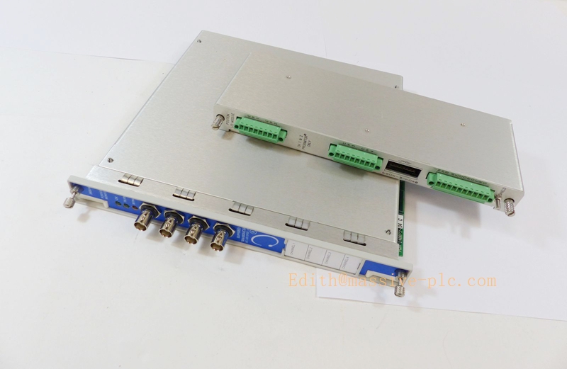
350045 140072-04
Product Introduction
140072‑04 is the front‑plug processing mainboard for the Bently Nevada 3500/45 Position Monitor, a core module within the 3500 machinery protection system. It is designed to monitor thrust position, differential expansion, case expansion, valve position and other displacement‑related parameters for steam turbines, gas turbines and large rotating machinery. This 4‑channel monitor interfaces with proximity probe rear I/O assemblies, acquires displacement signals from eddy‑current proximity transducers, provides real‑time position measurement, alarming and protection interlock. Compliant with API‑670 and SIL‑2 capable, it delivers critical machinery protection and condition‑based monitoring. It cannot operate standalone and must mate with matched rear I/O assembly and 3500‑series rack power supply.
Note: This module is dedicated for position/displacement measurement, not for vibration measurement. It supports dual‑probe differential expansion calculation for turbine shell‑rotor thermal expansion monitoring.
Typical Applications ‑ Thrust bearing position monitoring and protection for steam & gas turbine units ‑ Rotor‑to‑case differential expansion measurement ‑ Turbine case absolute expansion monitoring ‑ Valve stroke / actuator position monitoring ‑ Over‑position alarm and relay protection interlock ‑ Transmit real‑time position data to DCS, PLC or 3500 display system via rack backplane bus
Technical Specifications
| Item | Specification |
|---|---|
| Part Number | 3500/45 140072‑04 |
| Product Type | Position Monitor Front‑plug Mainboard |
| Compatible Rear I/O | 140471‑01, 140482‑01 (Standard Prox/Velom I/O assemblies) |
| Supported Transducers | Eddy‑current proximity probes |
| Channel Configuration | 4 input channels, organized as two independent channel‑pairs |
| Measurement Functions | Absolute position, differential expansion, case expansion |
| Transducer Excitation | −23 Vdc nominal |
| Frequency Response | 0‑1 kHz (low‑frequency position measurement) |
| Measurement Accuracy | ±1 % full‑scale |
| Alarm Logic | Independent Alert & Danger setpoints per channel‑pair; configurable alarm delay: 0‑60 seconds |
| Communication | 3500 rack backplane bus; Modbus RS485 |
| Power Consumption | Max 7.7 W, powered from rack backplane 24 VDC |
| Operating Temperature | −40 °C ~ +85 °C |
| Certifications | SIL‑2 capable, API‑670 compliant, CE / RoHS |
| Approximate Weight | 0.39 kg |
| Installation | Hot‑swappable front plug‑in module for standard 3500 rack slots |
Important Remark: Multimode function is NOT supported; cannot pair with multimode‑type I/O (169459‑xx /169715‑xx). Only standard prox‑type rear I/O assemblies are applicable. No on‑board intrinsic‑safety barriers; hazardous‑area sensors require external certified IS barriers.
Key Features
- Position‑dedicated monitoring algorithm: measures thrust position, differential expansion and case expansion for large turbine equipment.
- Differential expansion calculation: computes relative expansion between rotor and casing using two independent proximity probe channels.
- Full software configurability: measurement range, transducer sensitivity and alarm thresholds set via 3500 Rack Configuration Software.
- Hot‑swap capability: module replacement without powering down the entire 3500 rack.
- Dual‑level Alert / Danger alarm outputs with configurable time delay for protection relay interlock logic.
- Comprehensive built‑in diagnostics: transducer open‑circuit / short‑circuit detection, hardware self‑test, time‑stamped event log stored in non‑volatile memory.
- Front‑panel BNC buffered recorder outputs for on‑site debugging and signal verification.
- High‑EMI‑immunity industrial hardware design, adapted to harsh power‑plant environments.
Adaptive Quality Assurance and Test Protocol (AQAT)
4.1 Factory‑Side Adaptive QA Test
‑ Power‑on self‑diagnostic verification: validate hardware self‑test status and rack backplane‑bus communication. ‑ Channel‑wise signal‑injection test: simulate proximity displacement input signals, verify reading accuracy within tolerance range. ‑ Differential expansion function test: simulate dual‑channel displacement inputs to validate calculated differential expansion value. ‑ Alarm‑threshold verification: simulate over‑limit input signals, validate Alert / Danger alarm trigger and relay‑output action. ‑ Transducer‑fault simulation: open‑circuit / short‑circuit simulation to confirm fault‑alarm reporting. ‑ Powered temperature‑cycling burn‑in screening to eliminate early‑life failure risk. ‑ Generate formal factory test report prior to shipment.
4.2 Site‑Side Adaptive QA Procedure
‑ Installation Qualification (IQ): verify full mechanical locking between mainboard and matched rear I/O assembly; inspect rack grounding, analog‑power cable separation. For hazardous‑area projects, verify external IS‑barrier configuration. ‑ Operational Qualification (OQ): inject simulation signals at field‑terminals; cross‑validate position readings, differential expansion calculation results, alarm trigger consistency and DCS data display. ‑ Performance Qualification (PQ): monitor under real turbine operating conditions; compare module readings with reference instrument data. ‑ Adaptive retest: execute full‑channel verification after module replacement, cable modification or configuration download; archive test records for audit traceability.
All test documentation shall be retained for asset‑management and audit purposes.
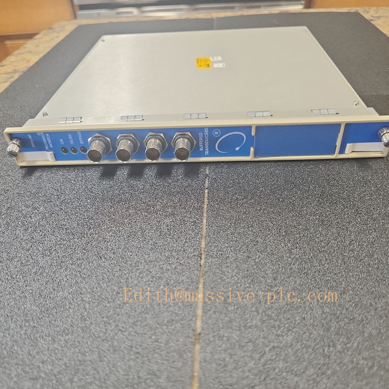
350045 140072-04
Field Engineer Technical Instructions
5.1 Installation Guidance
‑ Insert 3500/45 (140072‑04) front‑plug module into vacant slot of 3500 rack; fasten front‑panel latches to achieve full mechanical locking with rear‑side I/O assembly. ‑ Select matched rear‑I/O: 140471‑01 (internal screw termination) or 140482‑01 (external ribbon‑cable termination). Multimode‑series I/O assemblies are not compatible. ‑ Route proximity probe cables separately from high‑voltage power cables, follow maximum transducer‑cable‑length specifications. ‑ For hazardous‑area field‑sensors: install certified external intrinsic‑safety barriers, comply with local explosion‑proof wiring specifications. ‑ Follow site grounding specification: separate analog‑signal grounding from high‑power‑equipment grounding to minimize noise‑coupling interference.
5.2 Commissioning
‑ Complete mechanical installation of mainboard, rear‑I/O assembly and all field‑sensor wiring. ‑ Launch 3500 Rack Configuration Software, select module type 3500/45, configure transducer sensitivity, measurement range, Alert / Danger alarm setpoints and delay parameters. ‑ Enable differential‑expansion function if required, assign corresponding channel pairs. ‑ Download configuration to mainboard and perform module reset to activate parameters. ‑ Check raw measured values; perform alarm‑forcing test, confirm relay‑output action and DCS / HMI display consistency.
5.3 Typical Field Troubleshooting
‑ Transducer‑fault alarm: Inspect field‑cable open‑circuit / short‑circuit faults, terminal‑screw torque, transducer health condition. ‑ Incorrect position / expansion readings: Confirm software‑configured transducer‑sensitivity matches physical probe; check grounding and EMI interference; inspect probe‑cable integrity. ‑ Differential expansion calculation error: Verify two selected channels are correctly assigned in software. ‑ Communication loss: Confirm mainboard latches are fully locked; inspect rack backplane health and system‑controller operating status.
Warning: Bypass protection alarms only for short‑duration maintenance work. Restore full‑protection function before turbine unit returns to normal‑operation status.
5.4 Maintenance
‑ Observe front‑panel LED‑status indicators of 3500/45 mainboard during regular site inspection rounds. ‑ No user‑serviceable internal components; do not disassemble module housing. ‑ Keep complete configuration‑backup file for fast hardware replacement during future failure events.
Related / Similar Series Models
| Model | Brief Description |
|---|---|
| 3500/45 140072‑04 | Position Monitor Mainboard |
| 140471‑01 | Standard Prox/Velom internal‑termination I/O |
| 140482‑01 | Standard Prox/Velom external‑termination I/O |
| 3500/42M‑140482‑02 | Vibration Monitor Mainboard |
| 3500/46M‑176449‑06 | Hydro Turbine Monitor Mainboard |
| 3500/50 | Keyphasor module for phase reference and rotational‑speed acquisition |



 Start Chat




