
Description
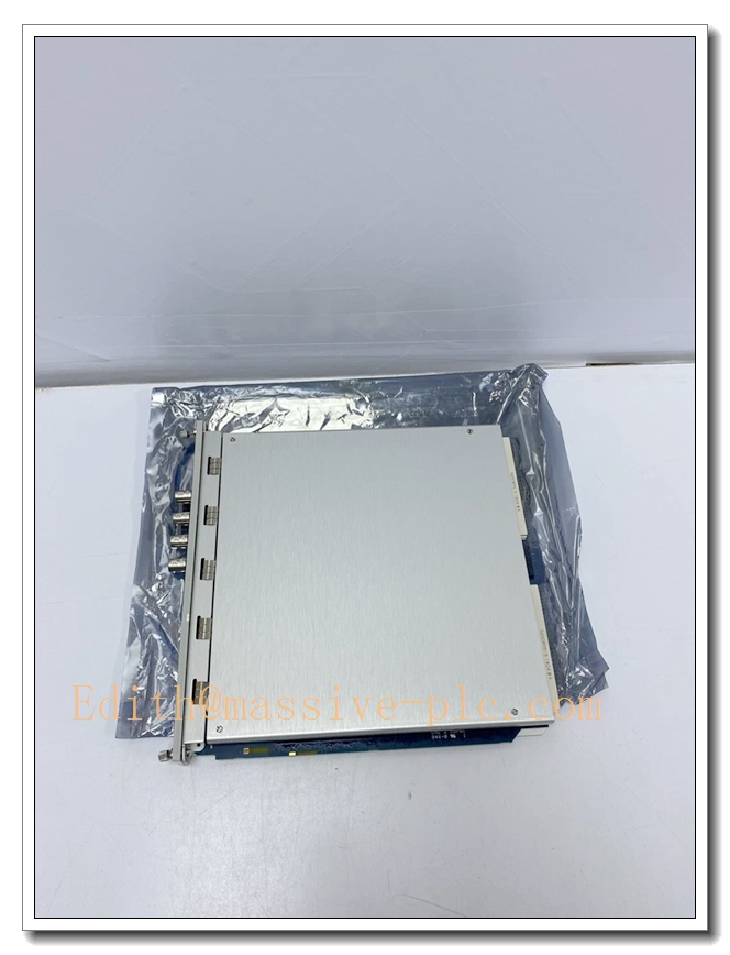
Bently Nevada 3500/42M (176449‑02) Proximitor / Seismic Monitor
Product Description
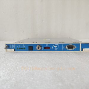
The 176449‑02 is the front‑plane monitor board for the Bently Nevada 3500/42M Proximitor/Seismic Monitor, a core four‑channel module within the 3500 machinery‑protection platform. It interfaces with proximity probes and seismic transducers (velocity sensors, accelerometers), performs signal conditioning, digital processing and measurement computation for rotating‑machine parameters. Each channel pair can be configured for radial vibration, thrust position, differential expansion, eccentricity, REBAM, velocity, acceleration and shaft‑absolute measurement. The module generates Alert / Danger alarm outputs against user‑defined thresholds, transmits measurement and alarm status over the rack backplane for machinery protection, emergency trip interlock and predictive‑maintenance analytics, and provides buffered transducer outputs for external oscilloscope or diagnostic tools. It must pair with matching rear I/O assembly for field sensor wiring connection.
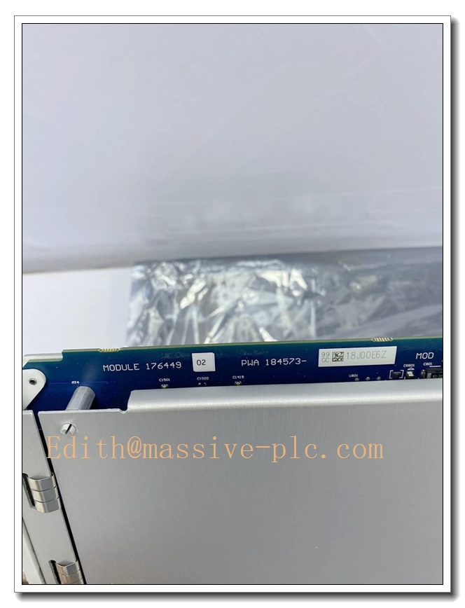
176449‑02
Technical Specifications
| Item | Parameter |
|---|---|
| Part Number | 176449‑02 (3500/42M Front Module) |
| Channel Count | 4 independent channels, configured in channel pairs (1‑2, 3‑4) |
| Supported Inputs | Proximitor proximity probes, Velomitor velocity transducers, accelerometers |
| Input Impedance | 10 kΩ (standard); parallel 50 kΩ for TMR bus‑wired mode |
| Buffered Output | One short‑circuit‑protected coaxial buffered transducer output per channel, 550 Ω impedance |
| Alarm Logic | Per‑channel programmable Alert and Danger setpoints; configurable alarm delay 0‑60 s |
| Measurable Parameters | Radial vibration, thrust position, differential expansion, eccentricity, REBAM, acceleration, velocity, shaft absolute, circular acceptance region |
| Power Consumption | Typical 7.7 W |
| Operating Ambient Temperature | ‑30 °C ~ +65 °C |
| Storage Temperature | ‑40 °C ~ +85 °C |
| Humidity | 5 %‑95 % RH, non‑condensing |
| Safety Certification | IEC 61508 SIL 2, API 670 compliant, CE, UL approvedBaker Hugh… |
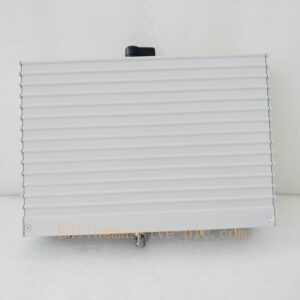
| Mechanical | Full‑height slot for 3500 rack; hot‑swap capable; weight approx. 0.82 kg |
| Configuration Tool | Bently Nevada 3500 Rack Configuration Software |
| Required Matching I/O | Corresponding rear I/O termination assembly for field sensor wiring |
Main Features and Advantages
Key Features
- Multi‑sensor compatible four‑channel design: accepts both eddy‑current proximity probe signals and seismic transducer inputs (velocity / acceleration), supporting both shaft‑relative and casing‑based vibration monitoring in one module.
- Pair‑wise flexible channel programming: channel pairs can run different measurement functions simultaneously, optimizing slot utilization inside the 3500 rack.
- Buffered transducer BNC outputs on front panel for on‑site waveform diagnostics without breaking field wiring.
- Dual‑level Alert / Danger alarms with adjustable time‑delay filtering to suppress transient noise‑triggered false trips.
- Built‑in continuous self‑diagnostics for probe fault, cable break and module hardware failure; front‑panel LED indicators for OK, Alarm, Bypass and Fault status for fast field troubleshooting.
- TMR‑architecture compatible, supports triple‑modular‑redundant protection loops for high‑safety critical turbo‑machinery projects.
- Hot‑swap function: module replacement without rack power‑down; fully interoperable with other 3500 series modules via rack backplane bus.
Core Advantages
- Consolidates shaft displacement and casing vibration monitoring within a single rack slot, reducing cabinet footprint and spare‑part inventory.
- Complies with API 670 turbo‑machinery protection standard, widely accepted for oil‑gas and power‑plant safety‑critical assets.
- High‑quality signal conditioning maintains measurement accuracy under heavy EMI‑prone industrial environments.
- Provides both protection‑oriented alarm outputs and raw diagnostic buffered signals, covering safety interlock and predictive‑maintenance requirements simultaneously.
- Seamless integration with 3500 relay, communication and display modules, simplifying overall system architecture.
Application Fields
- Oil & Gas: centrifugal compressors, gas turbines, steam turbines; monitoring radial vibration, thrust position and casing vibration for turbo‑machinery protection and ESD interlock.
- Power Generation: thermal‑power, combined‑cycle power plants; turbine‑generator bearing vibration, shaft thrust and differential expansion surveillance.
- Petrochemical: large process pumps, blowers, gearboxes and turbo‑expanders for rotating‑machinery condition monitoring and trip protection.
- Heavy Industry: steel, mining facilities for large motors, fans and critical rotating equipment health assessment.
- General industrial rotating machinery: implement early fault warning and machinery safety protection for high‑speed rotating assets.
Related Product Recommendations
- Matching rear I/O assembly: Corresponding rear termination I/O module for 3500/42M for field probe wiring termination.
- 3500/44M: Aeroderivative gas‑turbine dedicated vibration monitor module for gas‑turbine‑focused projects.
- 3500 system rack accessories: 3500/05 rack chassis, 3500/15 redundant power supply, 3500/32 /33 relay output modules, 3500/92 communication gateway.
- Field sensors: 3300XL series proximity probes, Velomitor velocity transducers, accelerometers.
- Companion monitors: 3500/61 temperature monitor, 3500/62 process‑variable monitor for comprehensive machine‑health supervision.
Installation and Maintenance
Installation
- Insert the 176449‑02 front monitor module together with its matched rear I/O assembly into a full‑height slot of Bently Nevada 3500 rack. For TMR redundant deployment, install three identical module assemblies in adjacent rack slots to satisfy voting‑logic requirements.
- Route proximity probe and seismic‑transducer shielded cables to rear‑I/O terminals. Separate low‑level sensor wiring from high‑power cables to minimize electromagnetic interference. Follow single‑point shielding‑grounding specifications.
- Configure measurement mode, sensor sensitivity, Alert / Danger alarm thresholds and filter parameters by 3500 Rack Configuration Software, then download configuration to rack backplane.
- Verify front‑panel LED status: solid OK lamp indicates normal module operation. Perform probe gap check and signal simulation test before commissioning to validate measurement accuracy and alarm‑trigger behaviour.
Maintenance
- Hot‑swap replacement is supported: set relevant channels to bypass status before extracting the module assembly; insert complete new matching front‑and‑rear assembly; reload configuration parameters if needed; rack power‑off is not required.
- Periodically inspect field transducer cables, extension cables and termination terminals for looseness, abrasion or corrosion.
- Routinely check front‑panel LED status; investigate Alarm, Bypass or Fault indications in timely manner.
- Keep rack ventilation unobstructed; ensure operating temperature and humidity stay within rated specifications.
- Perform periodic loop calibration: inject simulated vibration / displacement signals to verify measurement accuracy and alarm response.
- For defective hardware, return units to authorized service channels; do not disassemble internal circuit boards on‑site.

 Start Chat




