
Description
Bently‑Nevada 3500/42‑06‑00 Monitor Assembly (176449‑02 Main Board + 135489‑03 Internal‑Barrier I/O Module)
Product Description
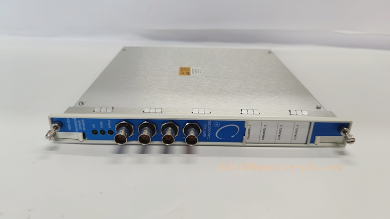
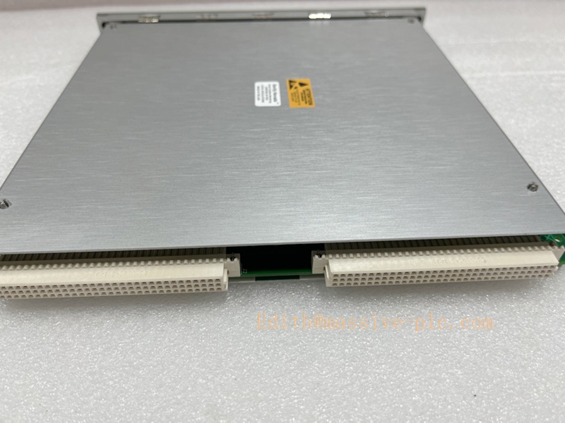
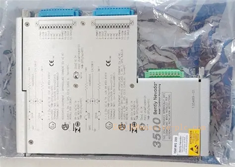
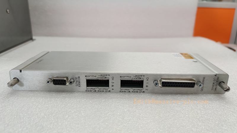
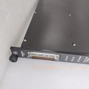
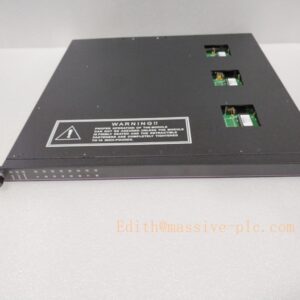
The 3500/42‑06‑00 is a complete Proximitor/Seismic monitor assembly within the Bently‑Nevada 3500 machinery‑protection system. The assembly consists of the front‑side main processor board 176449‑02 and the rear‑mount internal intrinsically‑safe barrier I/O daughter‑board 135489‑03.
The 176449‑02 main board is the core processing unit of the 3500/42‑06‑00 monitor. It accepts conditioned signals from the rear I/O module, executes measurement computation, alarm comparison, relay‑output logic, and communicates measurement data, status and diagnostic events to the rack backplane for the Rack Interface Module. It supports mixed‑input measurements for proximity probes and seismic transducers (velomitors / accelerometers).
The paired 135489‑03 is a 4‑channel internal‑barrier rear I/O module with internal screw‑terminal terminations, optimized for Velomitor velocity sensors. It provides energy‑limiting intrinsically‑safe interfaces for field transducers installed in Class I Div 2 / ATEX hazardous‑classified locations. This barrier I/O supplies transducer excitation, limits fault energy entering hazardous zones, and sends conditioned sensor signals to the 176449‑02 main board.
This assembly cannot operate standalone. It requires the mandatory 138257‑01 internal barrier earthing module for valid intrinsic‑safety certification. Original OEM production is discontinued; it is available only as aftermarket replacement spare for legacy hazardous‑area TSI installations.
Technical Specifications
| Item | Specification |
|---|---|
| Complete Assembly PN | 3500/42‑06‑00 |
| Front Main Board | 176449‑02 (3500/42M Proximitor / Seismic Monitor) |
| Rear I/O Daughter‑Board | 135489‑03 (4‑Ch Velomitor‑optimized Internal‑Barrier I/O, internal termination) |
| Mandatory System Component | 138257‑01 Internal Barrier Earthing I/O Module |
| Channel Count | 4 measurement channels per monitor assembly |
| Supported Transducers | 3300‑XL proximity probes, Velomitor velocity sensors, accelerometers |
| Measured Variables | Shaft radial vibration, thrust position, differential expansion, casing absolute vibration |
| Intrinsic‑Safety Parameters (from 135489‑03) | Uo=26.78 V, Io=90.17 mA, Po=842.89 mW |
| Termination | Built‑in internal screw terminals on rear I/O module |
| Alarm & Relay | Programmable alert / danger alarm thresholds; configurable relay outputs |
| Backplane Interface | Power, configuration and data communication via 3500 rack backplane |
| Form Factor | Front full‑height main board + rear full‑height plug‑in I/O daughter‑board |
| Operating Temperature | 0 °C ~ +65 °C (32 °F ~ +149 °F) |
| Storage Temperature | ‑40 °C ~ +85 °C (‑40 °F ~ +185 °F) |
| Relative Humidity | 5‑95 % RH, non‑condensing |
| Approximate Weight (complete set) | 0.66 kg (1.45 lbs) |
| Product Status | Discontinued OEM production, aftermarket spare‑part only |
Key Features & Benefits
- Integrated mixed‑measurement monitor with intrinsic‑safety barrier: Combines proximity and seismic measurement capability together with built‑in hazardous‑area energy‑limiting barrier circuit, eliminating the need for external Zener barrier cabinets. Optimized primarily for Velomitor casing‑vibration applications.
- Four‑channel flexible multi‑sensor support: Each channel can be independently configured for eddy‑current proximity probes, velocity velomitors or accelerometers, enabling combined shaft‑dynamic and casing‑vibration protection within one single monitor assembly.
- Internal field‑wiring termination: Field sensor cables connect directly to screw terminals integrated on 135489‑03 rear module, simplifying cabinet wiring and reducing spare‑part count for hazardous‑area loops.
- System‑level hazardous‑area safety compliance: When paired with 138257‑01 earthing module and certified field transducers, the assembly fulfills Class I Div 2 / ATEX intrinsic‑safety requirements. Improper earthing will void safety certification.
- Rich protection and diagnostic functions: Supports user‑configurable alert / danger alarm set‑points, relay logic outputs, comprehensive channel and loop diagnostics for transducer fault, barrier fault and ground‑loop detection.
- Hot‑swap maintainability: Rear‑side 135489‑03 I/O module supports hot‑swap replacement while rack remains powered; monitor main‑board replacement requires rack slot power removal. Compatible with existing 3500 rack firmware, RIM and power‑supply hardware for drop‑in spare‑part replacement.
Application Fields
- Machinery‑protection racks for steam turbines, gas turbines and centrifugal compressors in petrochemical refineries and natural‑gas processing plants, where casing‑mounted Velomitor seismic sensors and shaft proximity probes are located within ATEX / Class I Div 2 hazardous classified zones.
- Combined‑cycle power‑generation facilities requiring simultaneous monitoring of shaft radial‑vibration, thrust‑position and casing absolute‑vibration for rotating machinery inside explosive‑risk compartments.
- Legacy 3500 TSI system retrofit and spare‑part replacement for sites deployed with 3500/42‑06‑00 internal‑barrier monitor assemblies.
Related Recommended Products
- 138257‑01: Mandatory Internal‑Barrier Earthing I/O Module for intrinsic‑safety ground reference
- 135489‑02: General‑purpose mixed‑sensor internal‑barrier I/O alternative for 3500/42M main board
- 3500/20 (125744‑01): TMR Rack Interface Module for rack‑level communication, event logging and system diagnostics
- 3500/25: Keyphasor timing‑reference module for shaft‑speed and phase‑angle measurement
- 3500/15 series: Rack power‑supply assemblies for 3500 machinery‑protection rack
- 3300‑XL proximity probes, Velomitor velocity transducers: Hazardous‑area‑approved field sensors matching this monitor assembly
Installation and Maintenance
Installation
- Ensure the 138257‑01 barrier earthing module is correctly installed and rack protective‑earth connection is securely terminated before assembling the 3500/42‑06‑00 set. Missing or poor earthing invalidates intrinsic‑safety certification.
- Attach 135489‑03 rear barrier I/O module firmly onto the rear connector of 176449‑02 main monitor board. Insert the complete monitor assembly into a designated full‑height slot of the 3500 rack.
- Route hazardous‑area field transducer cables to built‑in screw terminals of 135489‑03. Strictly comply with maximum cable capacitance and inductance limits specified in Bently‑Nevada document 141495 (3500 Internal‑Barrier System Manual).
- Complete configuration via 3500 Rack Configuration Software: select transducer type for each channel, define alarm thresholds, enable internal‑barrier function and configure relay‑output logic.
- Apply rack power, verify module health status, and check rack event log for barrier‑fault, ground‑fault or transducer‑loop diagnostic alarms.
Important Note: 3500/42‑06‑00 assembly cannot operate without 138257‑01 barrier earthing module. Only 135489‑03 rear I/O supports hot‑swap; front main board 176449‑02 must be installed / removed with rack‑slot power disabled.
Maintenance
- Perform periodic visual inspection: check rear‑module terminals, connectors and barrier earthing bus for corrosion, dust accumulation and loose wiring connections.
- Review rack event log routinely for barrier‑fault, ground‑fault or transducer‑loop alarms; resolve field‑cable insulation degradation or transducer defects promptly.
- For rear I/O fault: hot‑swap 135489‑03 while rack remains powered; re‑verify earthing continuity and clear fault alarms after replacement.
- For main‑board fault: power‑down the corresponding rack slot before removing 176449‑02 main board. Re‑assemble with matched rear I/O module and restore configuration.
- Avoid mechanical shock and conductive contamination during module handling. Refer to official manual Doc 141495 for full hazardous‑area installation constraints and detailed troubleshooting procedures.

 Start Chat




