
Description
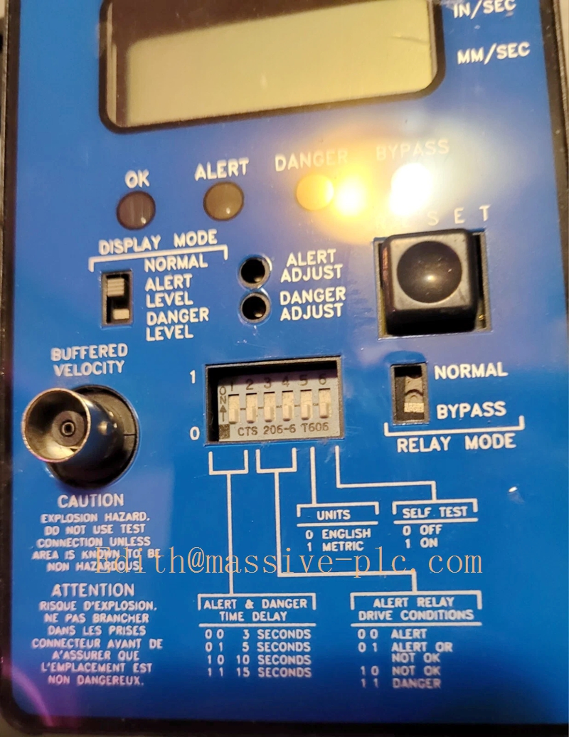
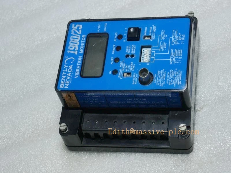
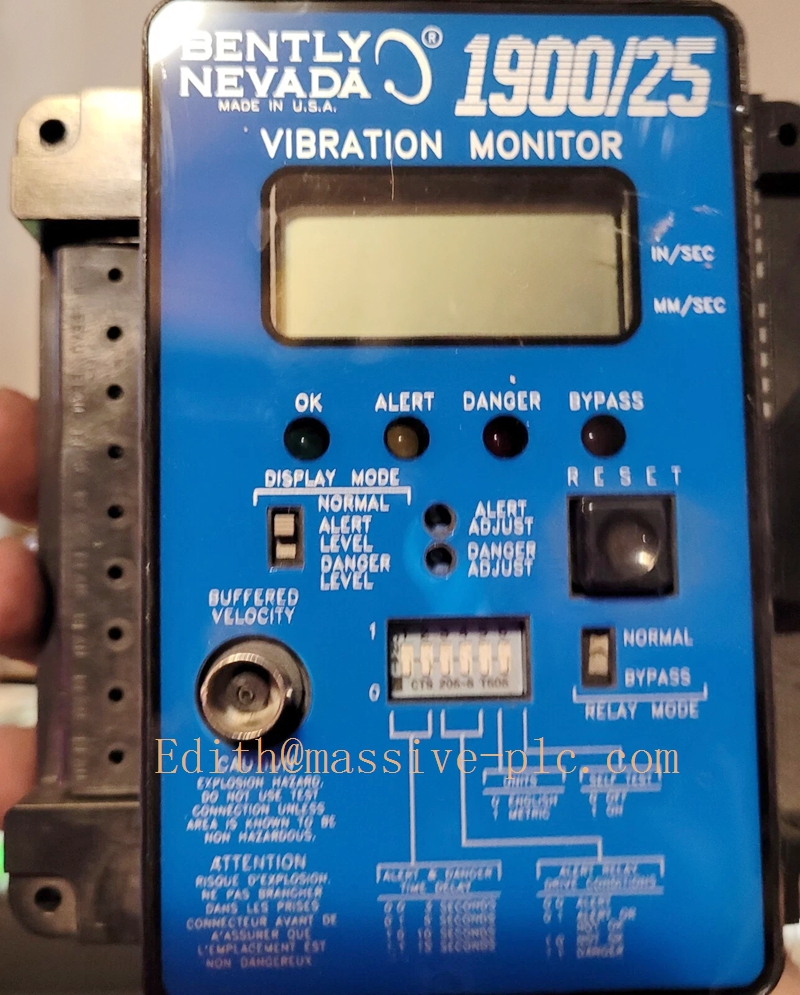
Bently Nevada 1900/25 Vibration Monitor
(Part No:141485‑01)
Model Introduction
Model: 1900/25 Single‑Channel Velocity Vibration Monitor Part Number: 1900/25 (internal drawing number 141485‑01) Device Type: Stand‑alone panel‑mount seismic vibration monitor for Trendmaster 2000 system Manufacturer: Bently Nevada (Baker Hughes) System Compatibility: Works with Trendmaster®2000 system via Trendmaster‑Pro interface; can run standalone without rack. Accepts signal from Trendmaster accelerometer sensors.
Cross‑reference note: ‑ 1900/25: Trendmaster‑Pro digital interface, NO 4‑20mA analog output ‑ 1900/27: Same hardware function, with 4‑20 mA output instead of Trendmaster‑Pro busm.bently-n…
Application Scenarios: Auxiliary machinery monitoring: fans, pumps, blowers. Measures housing seismic vibration (peak velocity). Provides local display, alarm relay outputs for machinery protection. Complies with API‑670. Country of Origin: United States Lifecycle Status: OEM discontinued, only aftermarket refurbished/spare‑parts available.
Important note: ‑ 1900/25 ≠ 3500/25. ‑ 1900/25: Stand‑alone velocity vibration monitor (Trendmaster‑2000 family). ‑ 3500/25: Enhanced Keyphasor module for 3500 rack system. These two cannot substitute each other.
BENTLY 190025
Technical Introduction
Core Functions
‑ Single‑channel input for Trendmaster 2000 accelerometer sensor. ‑ Integrate acceleration signal to peak velocity vibration value. ‑ Local digital display for vibration magnitude. ‑ Independent Alert / Danger alarm thresholds, relay contact outputs. ‑ Built‑in Trendmaster‑Pro communication interface for Trendmaster2000 host system. ‑ Front‑panel LED status indication: OK, Alert, Danger, Self‑test. ‑ Can work standalone or networked into Trendmaster2000 system.
Key Technical Specifications
| Item | Parameter |
|---|---|
| Measurement input | Trendmaster 2000 accelerometer |
| Measurement parameter | Peak velocity |
| Frequency range | 3 Hz ~ 1000 Hz |
| Communication | Trendmaster‑Pro bus (no 4‑20 mA on 1900/25) |
| Alarm output | Relay dry‑contact for Alert / Danger |
| Power supply | 18‑36 VDC |
| Mounting | Panel‑mount cutout installation |
| Operating temperature | ‑20 ℃ ~ +65 ℃ |
| Storage temperature | ‑40 ℃ ~ +85 ℃ |
| Humidity | 5‑95 % non‑condensing |
| Compliance | Industrial EMC, suitable for auxiliary machinery protection |
Mechanical Feature
Panel‑mount standalone unit, not a rack‑insert card. Installed into cabinet panel cut‑out. Front face with display, LED indicators and setup switches. Rear side for sensor wiring, power supply, relay terminals and Trendmaster‑Pro communication port. Not hot‑swap; power‑off before wiring modification.
Adaptive Quality Assurance & Test Protocol
3.1 Factory Adaptive QA Procedure
- Power‑on self‑test function verification.
- Input signal test with reference accelerometer simulator; verify velocity measurement accuracy.
- Alarm threshold test: Alert / Danger relay trigger & reset.
- Trendmaster‑Pro communication interoperability test.
- Relay contact output test.
- Environmental screening: temperature cycling, EMC noise immunity test.
- Serial‑number traceability, full functional‑test report archived.
3.2 On‑site Acceptance Test Protocol
- Visual inspection: Check unit housing, front display, rear terminals without damage or oxidation.
- Wiring check: Accelerometer sensor input, DC power supply, alarm relay wiring.
- Power‑on test: Confirm OK LED lit, self‑test passes.
- Set Alert / Danger alarm thresholds according to machinery specification.
- Inject simulated vibration signal, verify reading, alarm LED and relay action.
- If connected to Trendmaster2000 host: verify remote data reading via Trendmaster‑Pro bus.
- Record part‑number, hardware‑revision, test‑result snapshot for site QA archive.
BENTLY 190025
Field Engineer Technical Notes
Installation Guidance
‑ Panel‑mount installation; ensure adequate ventilation behind panel. ‑ Sensor cable: use matched Trendmaster accelerometer cable; keep cable routing away from high‑power interference cables. ‑ If analog 4‑20 mA signal required for DCS, select 1900/27 instead of 1900/25. ‑ 1900/25 Trendmaster‑Pro interface only works with Trendmaster2000 host; cannot connect directly to 3500 rack.
Field note: 1900‑series monitors are obsolete legacy auxiliary‑monitor hardware. Many sites replace 1900/25 with 2300‑series monitors or 3500‑rack monitor modules.
Commissioning Tips
‑ Set measurement unit (metric / inch) via front‑panel dip‑switch. ‑ Configure Alert / Danger threshold values matching machinery vibration alarm specification. ‑ Cross‑validate: local display reading should be consistent with Trendmaster2000 host reading.
Troubleshooting Common Issues
- No display / power fail: Check 18‑36 VDC power supply and rear‑terminal connection.
- Constant Danger alarm: Check accelerometer sensor and cable integrity; check sensor power.
- No Trendmaster‑Pro communication: Check bus wiring, address setting, bus termination resistor.
Diagnostic: Observe front‑panel LED status: OK / Alert / Danger / Self‑test.
Maintenance & Spare‑part Recommendation
‑ No field‑serviceable internal components; replace complete 1900/25 unit upon hardware failure. ‑ Spare‑part suggestion: Keep spare 1900/25 for legacy Trendmaster2000 system. If Trendmaster2000 host is retired, replace with 1900/27 (4‑20 mA) or 2300‑series monitor.
Related‑model comparison table
| Part Number | Description | Analog output | Communication |
|---|---|---|---|
| 1900/25 | Velocity Vibration Monitor | None | Trendmaster‑Pro bus |
| 1900/27 | Velocity Vibration Monitor | 4‑20 mA | None |
| 3500/25 | Enhanced Keyphasor Module for 3500‑rack | Depends on rear‑I/O | 3500 backplane bus |

 Start Chat




