
Description
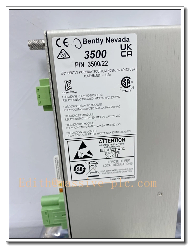
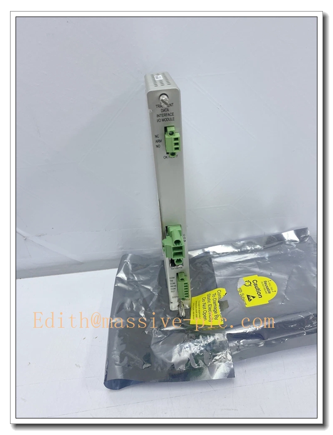
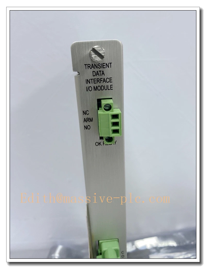
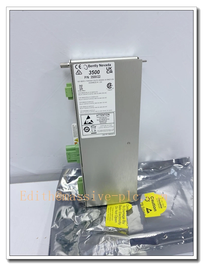
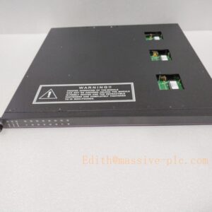
Bently Nevada 146031‑01 (3500/22M Transient Data Interface Ethernet I/O Module)
Product Description
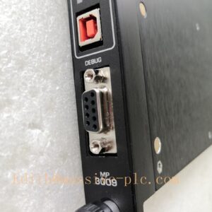
The 146031‑01 is the rear‑mounted 10Base‑T / 100Base‑TX Ethernet I/O assembly for the Bently Nevada 3500/22M Transient Data Interface (TDI, front board part number 138607‑01). Installed on the rear side of slot 1 (RIM slot) within the 3500 rack, it provides physical shielded‑RJ45 Ethernet connectivity. It combines the functions of legacy 3500/20 Rack Interface Module and TDXnet communication processor, serving as the primary high‑speed data gateway between the entire 3500 monitor rack and external host systems including System 1 predictive‑diagnostic software, 3500 Rack Configuration Tool, and plant‑side Modbus TCP clients. It transfers steady‑state measurement values, alarm events, and, with optional channel‑enable license, high‑resolution dynamic transient waveform data for rotating‑machinery fault analysis. This I/O module does not participate in the machinery‑protection safety trip path; communication failure will not inhibit monitor protection‑alarm and relay‑trip functions.
146031‑01
Technical Specifications
| Item | Parameter |
|---|---|
| Part Number | 146031‑01 (Ethernet I/O for 3500/22M TDI) |
| Mating Front Module | 138607‑01 (3500/22M TDI front‑plane board) |
| Network Interface | 10Base‑T / 100Base‑TX auto‑negotiation, shielded RJ‑45 |
| Supported Protocols | Modbus TCP/IP, proprietary TDXnet for System 1 software |
| Cable Requirement | Cat5e or better shielded twisted‑pair, max 100 m |
| Power Consumption | Powered by rack backplane; total 3500/22M assembly max 10.5 W |
| Required Rack Slot | Slot 1 (RIM slot, adjacent to power‑supply modules) |
| Data Capture | Standard: static steady‑state data; Dynamic / transient waveform: optional channel‑enable license required |
| Operating Ambient Temperature | ‑30 °C ~ +65 °C |
| Storage Temperature | ‑40 °C ~ +85 °C |
| Humidity | 5 %‑95 % RH, non‑condensing |
| Certifications | CE, UL, EMC industrial compliant |
| Mechanical | Rear I/O assembly for full‑height 3500 rack slot; hot‑swap capable; weight approx. 0.20 kg |
| Configuration Tools | Bently Nevada 3500 Rack Configuration Software, System 1 software |
Main Features and Advantages
Key Features
- 10/100 Mbps auto‑sensing shielded Ethernet interface for high‑speed machinery‑health data transmission to diagnostic host and plant network.
- Dual‑mode data acquisition: static measurement and alarm‑event data available as standard; dynamic waveform and transient capture activated by optional channel‑enable license key.
- Combines legacy RIM and TDXnet communication‑processor functions into one rack‑slot assembly, reducing total rack‑slot consumption.
- Supports Modbus TCP for seamless data export to DCS / SCADA historians, alongside proprietary TDXnet protocol for System 1 advanced machinery diagnostics.
- Hot‑swap capable for the complete 3500/22M front‑rear assembly; no rack power‑down required during replacement.
- Communication path is isolated from protection‑trip logic: network faults do not affect monitor alarm‑trip safety behaviour.
- Front‑panel LED status indicators on mating 138607‑01 board show module health, network link and communication activity for quick on‑site diagnostics.
- One TDI assembly per 3500 rack; it manages backplane communication for all monitor, relay and I/O modules within the rack.
Core Advantages
- Consolidates rack‑interface and high‑speed diagnostic‑data‑gateway functions, eliminating separate external TDXnet hardware.
- Provides two‑fold data output: safety‑oriented hard‑wired relay outputs for protection, plus Ethernet‑based high‑fidelity waveform data for predictive‑maintenance fault diagnosis.
- Modbus TCP support enables easy integration with mainstream plant control systems without additional gateway hardware.
- Hot‑swap maintainability minimizes downtime during communication‑module servicing.
- Communication‑path independence ensures machinery‑protection safety functions keep running regardless of network‑link conditions.
Application Fields
- Oil & Gas: centrifugal compressors, gas turbines, steam turbines; transmit vibration, temperature, thrust and process‑variable data to System 1 for rotor‑dynamic fault diagnostics.
- Power Generation: thermal‑power and combined‑cycle power plants; turbine‑generator condition‑data collection for predictive‑maintenance and historian logging.
- Petrochemical: refineries and ethylene plants; turbo‑expanders, large pumps and blowers continuous machinery‑health monitoring and event‑recording.
- Heavy Industry: steel, cement and mining facilities; critical rotating‑equipment fault‑trending and post‑event waveform playback for failure root‑cause analysis.
- General rotating‑machinery protection systems: acts as central rack communication hub for 3500 series TSI systems.
Related Product Recommendations
- 138607‑01: 3500/22M TDI front‑plane module, mandatory mating hardware for 146031‑01.
- Optional Channel‑Enable License: activates dynamic waveform / transient‑data capture function.
- 146032‑01: 100Base‑FX fiber‑optic I/O module alternative for long‑distance or heavy‑EMI industrial network environments.
- 3500 rack accessories: 3500/05 rack chassis, 3500/15 power‑supply modules.
- Companion monitor modules: 3500/42M vibration monitor, 3500/61 temperature monitor, 3500/62 process‑variable monitor, 3500/33 relay‑output module.
- Host software: Bently Nevada System 1 condition‑monitoring & diagnostic software, 3500 Rack Configuration Software.
Installation and Maintenance
Installation
- Mate rear‑I/O 146031‑01 with front‑plane 138607‑01 assembly, insert complete unit into Slot 1 (RIM slot) of the 3500 rack (adjacent to power‑supply slots), tighten front‑panel locking screws.
- Connect shielded Cat5e / Cat6 Ethernet cable to RJ‑45 port of 146031‑01; terminate cable shield per plant single‑point‑grounding specifications; separate signal wiring from high‑power cables to reduce EMI.
- Set IP‑address and network‑related parameters via 3500 Rack Configuration Software, download configuration to rack backplane. Apply channel‑enable license key if dynamic‑waveform capture is required.
- Verify front‑panel LED indicators on 138607‑01; confirm OK status and network‑link activity. Establish connection with System 1 or Modbus‑TCP‑based host system and validate data flow before commissioning.
Maintenance
- Hot‑swap replacement is supported: no rack power‑off needed; remove complete front‑rear paired assembly and install matched new 138607‑01 + 146031‑01 unit; reload network‑configuration and license parameters as needed.
- Periodically inspect Ethernet cable, shielding and RJ‑45 connector for damage, looseness or corrosion.
- Routinely check front‑panel LED status of the 138607‑01 front‑board; investigate communication‑fault indications promptly.
- Maintain unobstructed rack ventilation; keep operating temperature and humidity within rated specifications.
- Perform periodic communication‑connectivity test: verify steady‑state data, alarm‑event reporting and (if licensed) dynamic‑waveform transmission to host system.
- For defective hardware, return the complete front‑rear assembly to authorized‑service channels; do not disassemble internal circuits on‑site.


 Start Chat




