
Description
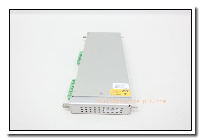
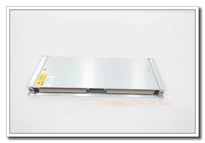
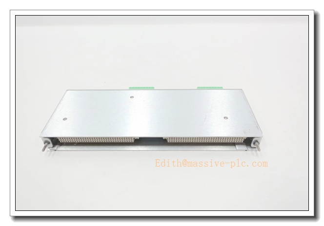
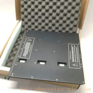
Bently Nevada 136294‑01(3500/61 Rear I/O Assembly, Internal Termination for RTD/Thermocouple)
Product Description
136294‑01 is the rear I/O assembly for Bently Nevada 3500/61 Temperature Monitor, which mates mechanically and electrically with front‑plane board 163179‑02 to form a complete temperature monitoring unit within the 3500 machinery‑protection rack system. It adopts internal‑termination design: field RTD and thermocouple sensor cables connect directly to screw terminals on this rear module. It provides signal conditioning routing for 6‑channel temperature inputs (supporting PT100 RTD and multiple thermocouple types), transmits sensor signals to the front monitor board through rack backplane interface. This I/O assembly is used for turbine/compressor bearing metal temperature, stator winding temperature and other thermal‑parameter acquisition, cooperates with vibration & process‑variable monitors to realize comprehensive machinery‑health supervision.
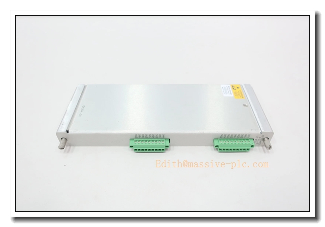
136294‑01
Technical Specifications
| Item | Parameter |
|---|---|
| Part Number | 136294‑01 (Rear I/O for 3500/61 Temperature Monitor, Internal Termination) |
| Mandatory Mating Front Board | 163179‑02 (3500/61 front‑plane temperature monitor) |
| Supported Sensors | RTD (PT100), multiple thermocouple types (J, K, T, E, R, S, B) |
| Channel Count | 6 temperature input channels |
| Termination Type | Internal termination, field wiring directly on rear screw terminals |
| Galvanic Isolation | Channel‑to‑backplane isolation |
| Power Source | Powered by rack backplane, no independent power supply |
| Operating Ambient Temperature | ‑30 °C ~ +65 °C |
| Storage Temperature | ‑40 °C ~ +85 °C |
| Humidity | 5 %‑95 % RH, non‑condensing |
| Certifications | CE, UL, API 670 compliant, SIL 3 capable in TMR configuration |
| Mechanical | Full‑height rear I/O assembly for 3500 rack; hot‑swap compatible; weight approx.0.20 kg |
| Configuration Tool | Bently Nevada 3500 Rack Configuration Software |
Main Features and Advantages
Key Features
- Internal‑termination rear I/O for 3500/61 temperature monitor; field RTD/thermocouple cables terminate directly on module terminals, eliminating extra external termination blocks and intermediate cables.
- Six‑channel temperature signal routing, compatible with PT100 RTD and mainstream thermocouple sensor types; sensor type selectable per channel by software configuration.
- Full hot‑swap capability when paired with front‑plane 163179‑02; the whole front‑rear assembly can be replaced without rack power‑down.
- Supports TMR triple‑modular‑redundant deployment; three identical sets of 3500/61 (163179‑02+136294‑01) can be installed in adjacent slots for high‑safety temperature‑protection loops.
- High‑isolation design reduces ground‑loop interference induced by long‑distance temperature‑sensor cabling in industrial sites.
- Seamless integration with the whole 3500 platform; temperature‑measurement values and Alert/Danger alarm status are transmitted over backplane to relay‑output modules and TDI communication module.
Core Advantages
- Internal‑termination structure reduces intermediate connection points, lowers field‑wiring fault risk, simplifies cabinet layout.
- Unified rack‑based temperature monitoring, no need for standalone temperature acquisition instruments; shares power, communication and relay resources with vibration & process‑variable monitors.
- TMR‑compatible architecture meets SIL 3 safety‑instrumented‑system requirements for critical turbo‑machinery bearing‑temperature protection.
- Hot‑swap maintainability minimizes equipment downtime during module‑fault maintenance.
- Complies with API 670 turbo‑machinery‑protection standard, widely adopted in oil‑gas, petrochemical and power‑generation industries.
Application Fields
- Oil & Gas: centrifugal compressors, gas turbines, steam turbines; bearing‑bush metal‑temperature monitoring for compressor‑station rotating assets.
- Power Generation: thermal‑power and combined‑cycle plants; turbine‑generator bearing temperature, stator winding temperature monitoring for machinery‑protection and predictive‑maintenance.
- Petrochemical: refineries, ethylene plants; turbo‑expanders, large process pumps and blowers bearing‑temperature acquisition and alarming.
- Heavy‑process industry: chemical plants, steel‑making facilities; critical rotating‑machinery thermal‑condition supervision.
- General rotating‑machinery protection: complements vibration and process‑variable monitors to deliver full‑scope machinery‑condition‑monitoring solution.
Related Product Recommendations
- 163179‑02: 3500/61 front‑plane temperature‑monitor board, mandatory mating part for 136294‑01.
- 136295‑01: 3500/61 rear I/O assembly with external‑termination, alternative for projects adopting external terminal‑block scheme.
- 3500 system accessories: 3500/05 rack chassis, 3500/15 redundant power supply, 3500/33 relay‑output module, 3500/22M TDI communication module.
- Field sensors: PT100 RTD, K‑type/J‑type thermocouples for bearing‑temperature measurement.
- Companion monitor modules: 3500/42M vibration monitor, 3500/62 process‑variable monitor.
Installation and Maintenance
Installation
- Physically mate rear‑I/O 136294‑01 with front‑plane 163179‑02; insert the complete front‑rear assembly into a full‑height slot of the 3500 rack. For TMR redundant configuration, install three identical assemblies in adjacent rack slots.
- Route shielded RTD / thermocouple field cables to screw terminals of 136294‑01. Separate low‑level temperature‑signal wiring from high‑power cables to suppress electromagnetic interference; follow single‑point‑grounding specifications strictly.
- Open 3500 Rack Configuration Software, configure each channel sensor type, engineering‑unit range, filter parameters, Alert/Danger alarm thresholds and alarm‑delay time, then download configuration to rack backplane.
- Verify front‑panel LED status of 163179‑02; solid OK lamp indicates normal module operation. Perform simulation test or on‑site sensor‑signal verification to confirm temperature‑reading accuracy and alarm‑trigger performance before commissioning.
Maintenance
- Hot‑swap replacement is supported: set related monitor channels to bypass status before extracting the complete front‑rear paired assembly; install new matched set of 163179‑02 +136294‑01, reload configuration parameters as needed; rack power‑off is not required.
- Periodically inspect rear‑module terminals and field‑sensor cables for looseness, oxidation, corrosion or insulation damage.
- Routinely observe front‑panel LED indicators of 163179‑02; investigate fault, bypass or abnormal‑alarm status promptly.
- Maintain unobstructed rack ventilation; ensure operating temperature and humidity stay within rated specifications.
- Conduct periodic loop‑verification: input reference‑temperature‑simulation signals to check measurement accuracy and alarm‑response behaviour.
- For defective hardware, return the complete front‑rear assembly to authorized‑service channels; do not disassemble internal circuits on‑site.



 Start Chat




