
Description
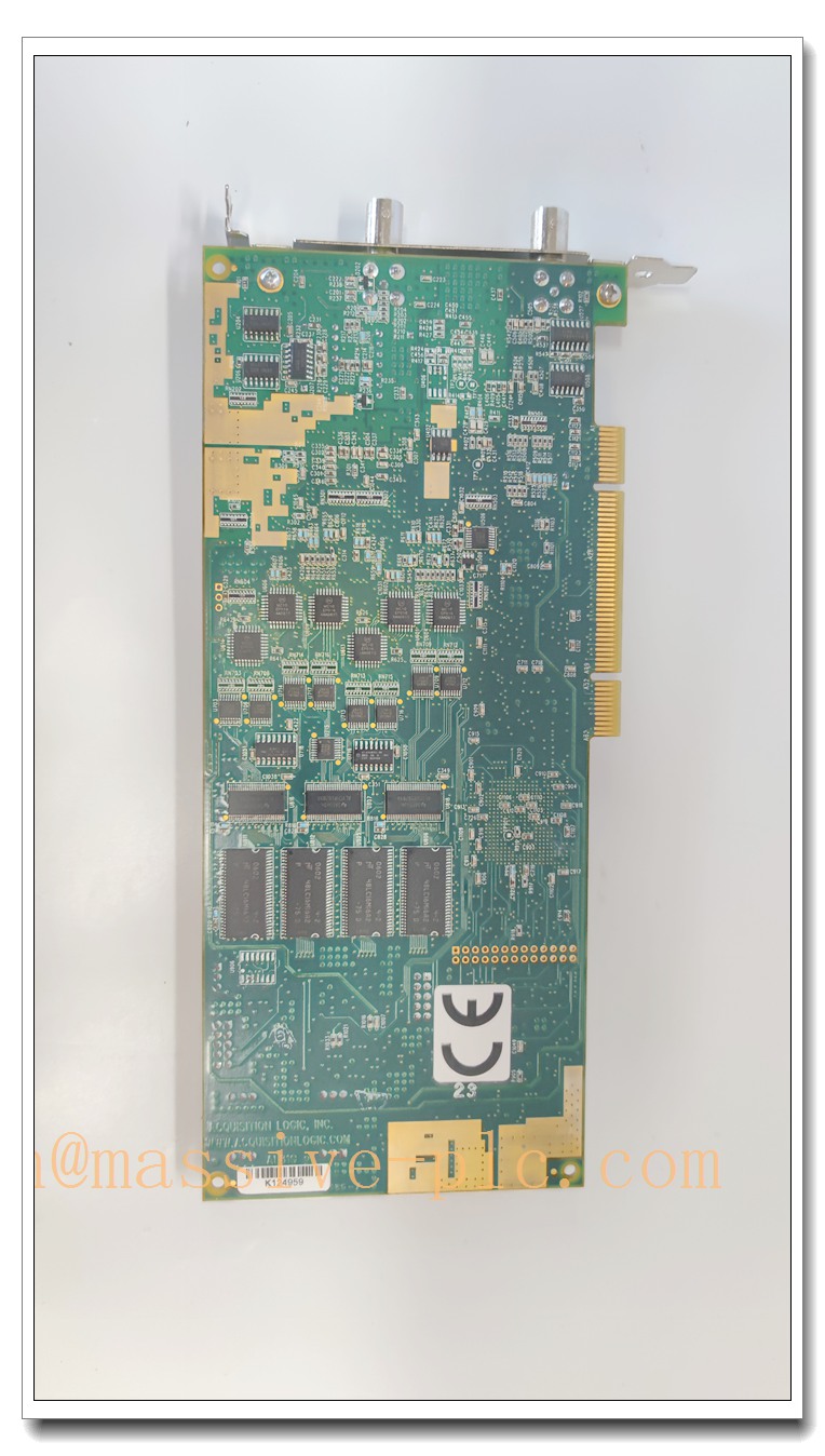
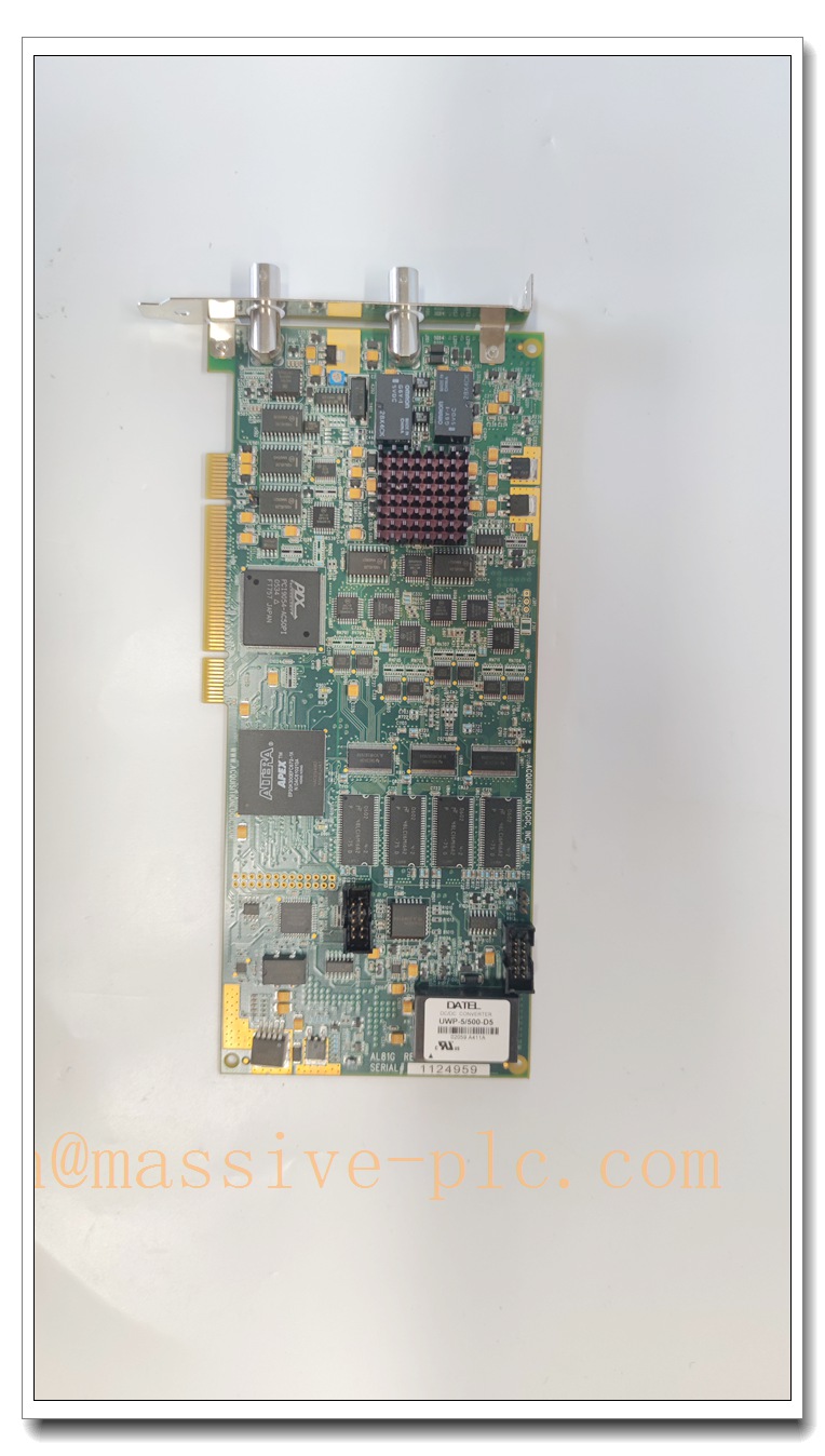
AL81G High‑Speed PCI Digitizer / Data Acquisition Board (AcquisitionLogic AL80 Series)
Product Core Introduction
The AL81G is a single‑channel high‑speed PCI analog‑to‑digital digitizer board manufactured by AcquisitionLogic, belonging to the AL80 series. Designed for capturing high‑frequency ultrasonic RF signals, it delivers up to 1 GS/s sampling rate with 8‑bit vertical resolution and approximately 40 dB dynamic range. Equipped with BNC analog input and trigger connectors plus large on‑board acquisition memory, this PCI card supports multiple trigger modes and encoder position synchronization, widely deployed in non‑destructive testing (NDT), ultrasonic scanning and precision measurement systems. It supports DMA burst data transmission and programmable DSP functions for waveform interpolation, peak detection and gain/offset adjustment, enabling high‑fidelity capture of fast transient analog waveforms in laboratory and industrial inspection environments.
Main Technical Specifications
| Technical Parameter | Specification Value |
|---|---|
| Model | AL81G (AcquisitionLogic AL80 Series) |
| Channel | Single analog input channel |
| ADC Resolution | 8-bit |
| Max Sampling Rate | 1 GS/s (1 GigaSample/second) |
| Input Bandwidth | DC to 350 MHz |
| Input Impedance | 50 Ω |
| Input Voltage Range | 125 mV / 250 mV / 500 mV / 1 V peak‑to‑peak, selectable |
| On-board Memory | 64 MSamples standard, optional 256 MSamples |
| Bus Interface | 32-bit PCI, 33 MHz |
| Data Transfer | DMA Scatter/Gather, burst rate up to 133 MB/s |
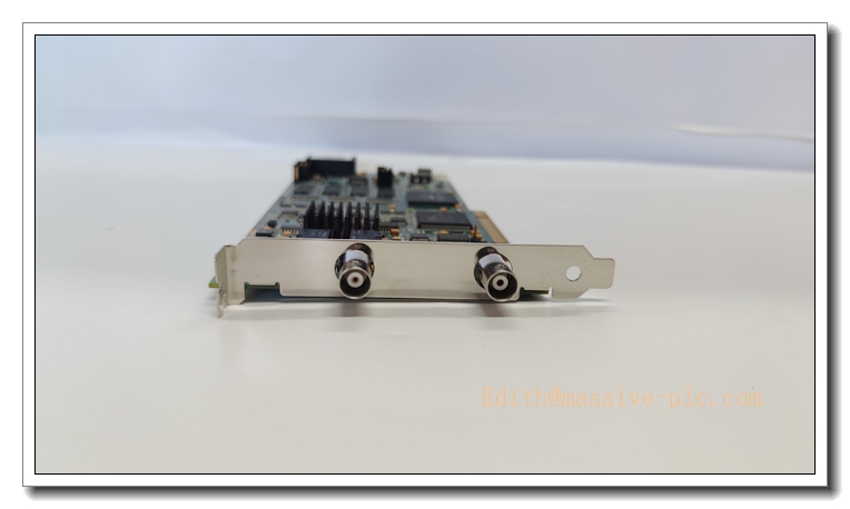
| Connectors | BNC analog input, BNC trigger I/O |
| Trigger Modes | Threshold trigger, encoder trigger, software, internal & external trigger |
| DSP Functions | ×2 / ×4 interpolation, programmable peak detector, gain & offset control |
| Power Requirement | +5 V / 2.0 A; +3.3 V / 4.5 A; +12 V |
| Operating Temperature | 0 ℃ ~ +55 ℃ |
| Storage Temperature | -40 ℃ ~ +85 ℃ |
| Operating Humidity | 5% ~ 90% RH, non‑condensing |
| Software Support | Windows / Linux, compatible with LabVIEW, MATLAB, C/C++ SDK |
| Compliance | CE, FCC |
Brand Same‑Series Model Recommendation
- AL80G: Entry high-speed digitizer, single channel, 500 MS/s sampling rate, smaller onboard memory, suitable for basic ultrasonic inspection and low‑frequency RF capture, cost‑effective for standard scanning systems.
- AL82G: Dual‑channel high-speed digitizer, 1 GS/s per channel, synchronous dual acquisition, ideal for dual-probe ultrasonic inspection and differential signal measurement.
- AL83G: Enhanced high-bandwidth version, extended analog bandwidth up to 500 MHz, optimized for high-frequency ultrasonic microscopy and advanced material flaw detection.
- AL81G‑256: AL81G variant with upgraded 256 MSample onboard memory, for long continuous waveform recording without frequent PC memory transfer.
AL81G
Professional Quality Control Test Standard Operating Procedures (SOP)
5.1 Component Incoming Inspection
All active ICs, analog front‑end chips, memory devices, PCB substrates and BNC connectors are inspected against component datasheets. Electrical parameter sampling and solderability verification are performed; non‑conforming parts are rejected and traceability records created for every batch.
5.2 PCBA Assembly & Visual Inspection
After SMT and through-hole soldering, full visual inspection checks for cold solder joints, bridging, component misalignment and mechanical damage. High‑resistance continuity testing is performed for power and signal traces.
5.3 Burn-in Test
72 hours powered burn-in at 45 ℃ ambient temperature. Continuous sampling loop runs on the board; sampling integrity, trigger stability and memory read/write performance are logged. Boards showing drift, dropouts or communication failures are screened out.
5.4 Full Performance Calibration & Parameter Test
Use high‑frequency signal generators and oscilloscope reference instruments to calibrate gain, offset, vertical linearity and trigger threshold. Verify actual sampling speed, bandwidth, input impedance and DMA throughput. All parameters must meet datasheet tolerance limits.
5.5 Environmental Stress Screening
Temperature cycling (0 ℃ ↔ +55 ℃), humidity exposure and random vibration test per IEC 60068 standards to verify mechanical stability and signal integrity under simulated transport and operating stress.
5.6 Final Functional & Factory Acceptance Test
Complete system test in a host industrial PC: PCI enumeration, driver loading, trigger capture, encoder sync and DSP function validation. Appearance, label and accessory check. Only fully qualified units are packed for shipment.
New Module Installation Guidelines
6.1 Pre-Installation Preparation
- Power off the host PC and disconnect mains power.
- Wear anti-static wristband/gloves; place the board on anti-static mat.
- Inspect AL81G PCB for physical damage, bent pins or connector contamination.
- Confirm PC has available 32-bit PCI slot, compatible OS and reserved driver installation folder.
6.2 Hardware Installation
- Remove the PCI slot backplate from PC chassis.
- Hold the board by its metal bracket only; avoid touching PCB traces or components.
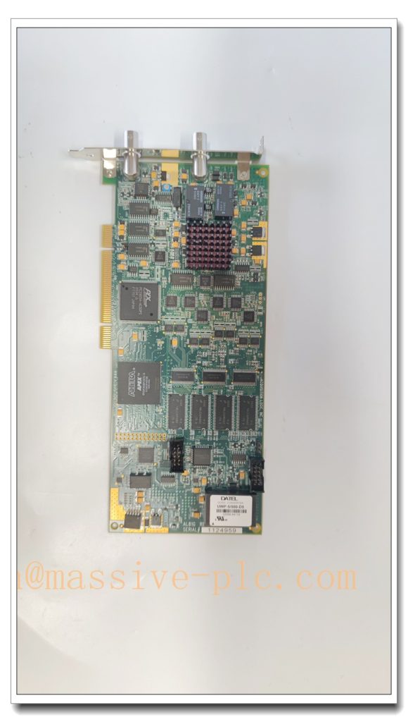
- Align PCI edge connector with the motherboard PCI slot, press firmly until fully seated.
- Secure the metal bracket with chassis screw.
- Connect BNC cables for analog input and trigger signal as required.
6.3 Post-Installation Software Setup & Commissioning
- Power on PC, install device driver and SDK software.
- Launch acquisition software to verify PCI enumeration and board recognition.
- Perform self-calibration routine for gain and offset.
- Inject reference test signal to validate sampling, trigger and waveform capture.
- Test encoder synchronization if used for scanning systems; confirm position-tagged waveform capture.
- Run continuous acquisition burn-in for 30 minutes before formal operation.
AL81G
Application Scenarios & Product Characteristics
7.1 Application Scenarios
- Ultrasonic Non-Destructive Testing (NDT): Automated scanning for metal flaw detection, thickness measurement, composite laminate inspection.
- Ultrasonic Microscopy: High-resolution material characterization and coating evaluation.
- Laboratory RF / transient waveform capture: Laser pulse, high-frequency sensor signal recording.
- Automated scanning systems: Motion-synchronized data acquisition with quadrature encoder position feedback.
- Aerospace & advanced material quality inspection.
7.2 Key Characteristics
- Ultra-high sampling rate for capturing fast ultrasonic RF waveforms.
- Built-in encoder input links waveform data directly to scanner position for C-scan imaging.
- Large onboard memory reduces PCI bus bottleneck for long capture records.
- Multiple flexible trigger modes for event-based waveform capture.
- Onboard DSP reduces PC processing load via interpolation and peak detection.
- Standard PCI interface, easy integration into industrial and laboratory PCs.
- Rugged analog front-end with controlled 50 Ω input impedance for high-frequency signal integrity.
FAQ (Frequently Asked Questions)
A1: Check PCI slot seating and power supply. Verify driver compatibility and OS version. Reseat the board; test in another PCI slot. Confirm no resource conflict in Windows device manager.
Q2: Waveform shows high noise / unstable baseline. A2: Check 50 Ω termination; inspect BNC connectors for loose contact or contamination. Use shielded coaxial cables. Separate analog signal path from power/relay noise sources. Re-run board self-calibration.
Q3: Trigger fails to capture waveforms reliably. A3: Verify trigger source selection and threshold level. Check trigger signal amplitude and edge polarity. Confirm impedance matching on trigger BNC input. Switch to software trigger for troubleshooting.
Q4: Data transfer is slow or samples drop out during long capture. A4: Confirm DMA mode is enabled. Check PCI bus master support and available system RAM. Reduce record length or use streaming transfer settings. Update driver and chipset firmware.
A5: Yes. The dedicated encoder input synchronizes waveform acquisition with scanner position, which is core for ultrasonic C-scan NDT applications.
A6: No. It is a standard PCI board. Always power down the host PC before installation or removal to avoid hardware damage.


 Start Chat




