
Description
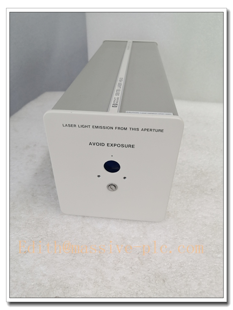
Agilent (Keysight) 5517B Dual-Frequency HeNe Laser Head for Laser Interferometer Metrology
Product Core Introduction
The 5517B is a stabilized Zeeman-split dual-frequency Helium-Neon laser head originally manufactured by Agilent (later rebranded Keysight). It outputs 632.991 nm vacuum wavelength laser beam, serving as the optical source for high-precision laser interferometer measurement systems. With reference frequency 1.9–2.4 MHz and maximum measurable linear velocity up to 538 mm/s, this laser head delivers excellent wavelength stability for sub-nanometer displacement measurement. It integrates laser tube, frequency stabilization circuitry, reference optical sampler and internal HV power supply within one compact housing. Widely deployed in semiconductor lithography stages, CMM, machine tool calibration and precision metrology equipment. The 5517B is end-of-life from OEM; available stock consists of tested refurbished and surplus spare units for legacy precision motion systems.
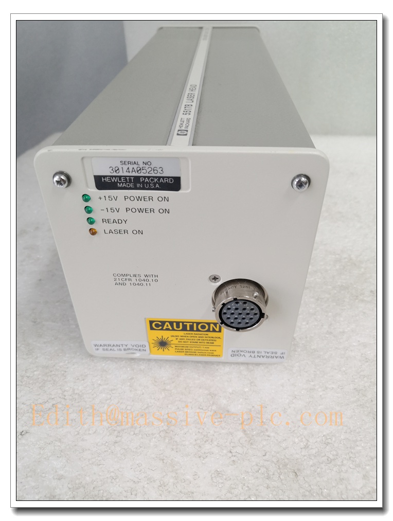
Agilent 5517B
Main Technical Specifications
| Technical Parameter | Specification Value |
|---|---|
| Model | 5517B (Agilent / Keysight) |
| Laser Type | Zeeman-split dual-frequency HeNe laser, Class II |
| Vacuum Wavelength | 632.991 nm |
| Reference Frequency | 1.9 ~ 2.4 MHz (Option H10: 2.2~2.4 MHz) |
| Max Measurable Linear Velocity | 538 mm/s |
| Beam Diameter | 6 mm nominal |
| Beam Height | 79.5 ±1.0 mm |
| Optical Output Power | Min 120 µW; Max 1 mW |
| Wavelength Stability | 2 ppb (1 hour typical); 20 ppb lifetime |
| Wavelength Accuracy | ±0.1 ppm standard |
| Power Supply | +15 VDC ±0.3 V @ max 3.0 A; -15 VDC ±0.3 V @ max 0.3 A |
| Heat Dissipation | 23 W steady operation; 35 W during warm-up |
| Warm-up Time | 90 minutes for full wavelength stabilization |
| MTBF | >50,000 hours typical |
| Net Weight | 3.4 kg (7.5 lb) |
| Operating Temperature | 15 ℃ ~ +35 ℃ |
| Storage Temperature | -40 ℃ ~ +65 ℃ |
| Operating Humidity | 5% ~ 80% RH, non-condensing |
| Compliance | 21 CFR Laser Safety, CE |
| Lifecycle Status | OEM Discontinued, aftermarket tested spare only |
Brand Same‑Series Model Recommendation
- 5517A: Lower reference frequency, max velocity 411 mm/s, longer warm-up time, for low-speed precision measurement.
- 5517C: Higher reference frequency (2.4–3.0 MHz), max velocity 696 mm/s, optional 3mm /9mm beam, upgrade for faster stage motion.
- 5517D: Higher reference frequency 3.4–4.0 MHz, for ultra-high-speed interferometer scanning systems.
- 5517BL: Low-power variant of 5517B, same mechanical footprint, suitable for low-light optical path setups.
- N1211A: Modern Keysight replacement laser head, digital stabilization, shorter warm-up, recommended for long-term system migration.
Professional Quality Control Test Standard Operating Procedures (SOP)
5.1 Incoming & Visual Inspection
Inspect laser tube, optical windows, internal PCBs, high-voltage components and connectors. Visual check for window scratches, contamination, burnt circuit traces and housing damage. Continuity and isolation test for high-voltage circuits. Batch traceability records are retained.
5.2 Low-Voltage Power-On Pre-Test
Apply ±15V control power. Verify power supply regulation, internal boot sequence, status indicator and reference signal output. Check for abnormal noise, corona discharge or overheating before laser tube ignition.
5.3 Stabilization & Burn-in Test
90 minutes initial warm-up followed by 48-hour continuous burn-in. Monitor reference frequency, optical power and wavelength drift continuously. Units with power fluctuation, frequency drift or unstable laser mode are rejected.
5.4 Optical & Metrology Calibration
Use wavelength meter and optical power meter to calibrate laser wavelength, beam power and reference frequency. Verify beam collimation, beam profile and polarization purity. Validate shutter function and reference sampler signal quality.
5.5 Environmental Stress Screening
Temperature cycling (15 ℃ ↔ 35 ℃), humidity soak and low-level random vibration per IEC 60068, simulating transportation and laboratory operating conditions. Check optical alignment and frequency stability after stress.
5.6 Final Acceptance Test
Integrate laser head with interferometer receiver and optics. Validate quadrature signal output, displacement measurement and velocity tracking. Complete appearance, label and accessory inspection. Passed units are packed with anti-vibration packaging.
New Laser Head Installation Guidelines
6.1 Pre-Installation Preparation
- Power off the interferometer controller and implement LOTO; remove ±15V power supply.
- Wear lint-free gloves and anti-static wristband. Do not touch optical window surface.
- Inspect laser window for dust, scratches or contamination. Confirm mechanical mounting footprint matches original unit.
- Prepare vibration-isolated optical base, torque driver and shielded power cables.
- Secure the installation area against strong air turbulence, direct sunlight and acoustic vibration.
6.2 Mechanical Installation
- Mount laser head on vibration-isolated base with specified torque. Keep laser level and stable.
- Align beam height to 79.5 mm to match existing optical path.
- Route shielded ±15V power cable; separate power cable from optical signal cables to avoid noise coupling.
- Confirm adequate airflow around housing for heat dissipation; do not block ventilation gaps.
6.3 Post-Installation Commissioning
- Double-check wiring polarity and grounding before energizing.
- Apply ±15V power and wait full 90-minute warm-up for wavelength stabilization.
- Verify laser beam output, reference frequency and optical power reading.
- Align beam with interferometer optics, check receiver quadrature signal quality.
- Perform linear displacement test and velocity scan test. Run continuous 30–60 min stability test before production measurement.
Important Safety Note: This product is Class II laser. Avoid direct eye exposure to laser beam. Internal high voltage exists even after power-off. Only qualified metrology technicians can perform replacement and service.
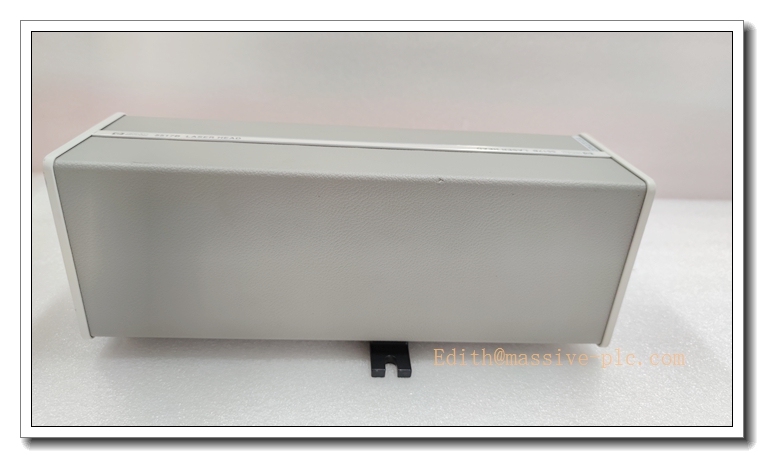
Agilent 5517B
Application Scenarios & Product Characteristics
7.1 Application Scenarios
- Semiconductor manufacturing: Wafer stage positioning, lithography and inspection tool metrology
- Precision machine tool calibration, linear axis accuracy verification
- Coordinate Measuring Machines (CMM)
- Optical metrology laboratories and calibration standards
- Flat panel display & precision optical positioning systems
7.2 Key Characteristics
- Dual-frequency Zeeman HeNe laser, immune to direction ambiguity for interferometry
- High wavelength stability for nanometer-level displacement measurement
- Integrated reference sampler for real-time wavelength compensation
- Compact all-in-one housing containing laser tube, HV supply and stabilization electronics
- Standard beam size 6 mm, compatible with legacy Agilent interferometer optics
- Long MTBF, proven reliability for 24/7 precision metrology
- Critical spare part for legacy laser interferometer measurement systems (OEM discontinued)
FAQ (Frequently Asked Questions)
Q1: Laser powers up but no beam output. A1: Check ±15V power supply voltage and current limit. Inspect internal laser tube health and status LED. Verify no interlock or shutter blocking the beam.
Q2: Measurement readings drift after power-on. A2: 5517B requires full 90-minute warm-up. Check air turbulence and temperature variation around optical path. Recheck wavelength stabilization status. Clean laser window if contaminated.
Q3: Interferometer loses signal at high stage velocity. A3: Confirm 5517B max velocity limit (538 mm/s). Check reference frequency signal cable shielding and receiver alignment. Reduce stage velocity if exceeding rated limit.
Q4: Laser optical power gradually drops over time. A4: HeNe tube life is finite. Check window contamination, dust accumulation. If power falls below minimum specification, laser tube replacement is required.
Q5: Can I replace 5517B directly with 5517C? A5: Mechanical footprint is compatible, but reference frequency differs. Interferometer receiver parameters must be reconfigured and optical alignment re-tuned.
Q6: Is hot-swap allowed? A6: NOT PERMITTED. Power must be fully cut before removal. Internal high voltage remains after shutdown.



 Start Chat




