
Description
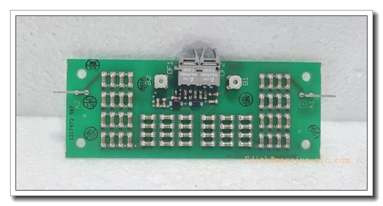
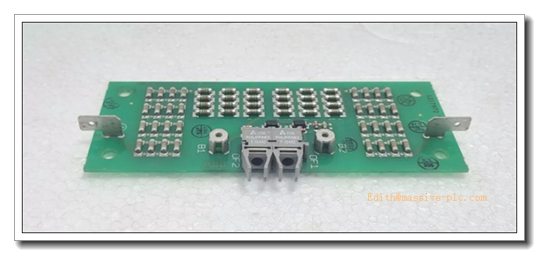
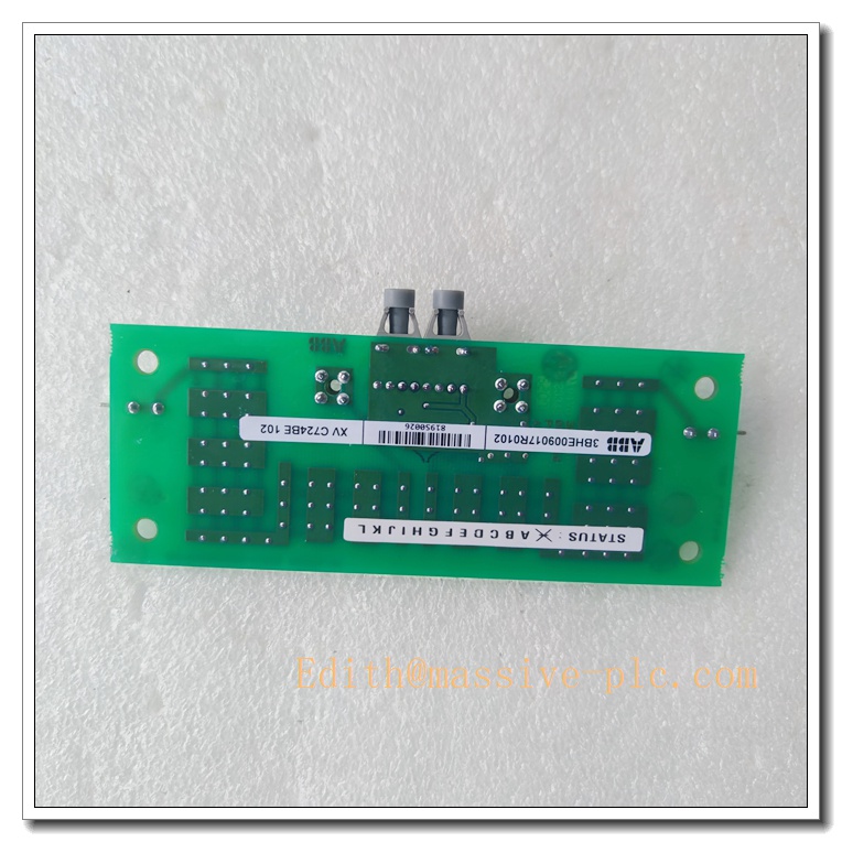
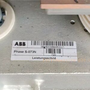
ABB XVC724BE102 3BHE009017R0102 Fiber Optic Interface Board
Product Core Introduction
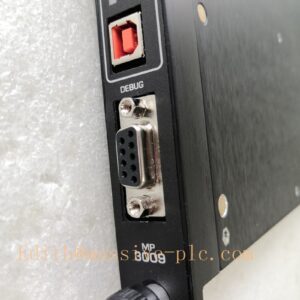
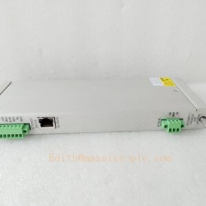
The XVC724BE102 (3BHE009017R0102) is a high-speed fiber optic interface board designed for ABB AC800PEC / PEC800 & UNITROL excitation control platform. It acts as the optical signal transceiver between the main controller and power unit, converting electrical control pulses into optical signals to achieve galvanic isolation between low-voltage control rack and high-power converter sections. It transmits gate drive commands, device status feedback and hardware interlock protection signals. Thanks to fiber transmission, it effectively suppresses EMI interference, making it ideal for power plant excitation, medium voltage converters and heavy industrial power conversion systems.
XVC724BE102 3BHE009017R0102
Main Technical Specifications
- Part No: 3BHE009017R0102
- Model: XVC724BE102
- Type: Fiber Optic Interface Board
- Supply Voltage: 24 VDC (19.2 ~ 30 VDC)
- Typical Power Consumption: 7 W
- Optical Ports: Multi-channel fiber optic transceivers
- Isolation: High voltage galvanic isolation via optical fiber
- Bus Interface: Modulebus backplane connection
- Response Time: Fast hardware interlock < 1µs
- Operating Temperature: -20 ℃ ~ +60 ℃
- Storage Temperature: -40 ℃ ~ +85 ℃
- Humidity: 5% ~95% RH, non-condensing
- Protection Class: IP20 (cabinet mounted)
- Certifications: CE, cULus
Recommended same-series ABB models
- UFC912A101 (3BHE039426R0101) – EOI emitter output interface board
- PCD231B (3BHE025541R0101) – Excitation control board
- PCD232A (3BHE022293R0101) – PEC800 control module
- GFD233A (3BHE022294R0101) – Feedback signal board
- GDC801B101 (3BHE051592R0101) – Gate drive digital output board
- SPBRC410 – PEC rack controller
Quality Control Test SOP
- Visual Inspection: Check PCB, soldering, fiber ports, edge connector and marking, no scratches, corrosion or component damage.
- Continuity Test: Verify backplane connector continuity and circuit integrity.
- Optical Power Test: Measure transmit & receive optical power of each fiber channel.
- Power-on Burn-in Test: 24VDC powered for 4h at rated temperature, monitor LED status and board temperature.
- Channel Communication Test: Send & receive optical pulse signals, validate signal waveform and bit error rate.
- Hardware Interlock Test: Trigger emergency interlock signal, verify instant protection response.
- Modulebus Communication Test: Connect with PEC800 controller to confirm stable data exchange.
- EMC Immunity Test: IEC 61000 ESD, EFT and surge immunity test.
- Serial number archiving and anti-static packaging.
XVC724BE102 3BHE009017R0102
New Module Installation
WARNING: Cut off all rack power and wear ESD wristband before handling.
- Disconnect main cabinet power and 24VDC auxiliary supply.
- Release retaining latches, pull out the old XVC724BE102 smoothly.
- Align edge connector with backplane slot, insert fully and lock the latches.
- Install fiber optic cables strictly following the wiring drawing. Do not bend fiber below the minimum bending radius. Keep fiber end faces clean.
- Double-check fiber Tx/Rx port matching, confirm no loose connection.
- Restore power, load matching firmware for UNITROL / ACS6000 system.
- Run optical channel test and protection interlock verification before online commissioning.
Note: This module does NOT support hot swap in excitation and medium voltage converter racks.
Application Scenarios & Features
Application Scenarios
- UNITROL 6000 generator excitation systems for thermal / hydro power plants
- ABB ACS6000 medium voltage high-power converters
- Metallurgy rolling mill high-power drives
- STATCOM / SVC reactive power compensation devices
- AC800PEC / PEC800 control cabinets
Key Features
✅ Fiber-optic transmission, excellent anti-electromagnetic interference performance ✅ High-speed hardware interlock for rapid fault protection ✅ High voltage isolation between control side and power side ✅ Multi-color LED indicators for power, running and channel fault diagnosis ✅ Compact slide-in rack design for convenient spare replacement ✅ Fully compatible with ABB PEC800 controller ecosystem
FAQ
Q1: Fiber link failure alarm after power-up? A: Check fiber cleanliness, inspect fiber end face for dust or scratches. Verify Tx/Rx port pairing, and check fiber bending condition. Replace fiber cable if damaged.
Q2: Some optical channels have unstable signal? A: Re-seat the fiber connector. Check if the module’s optical transceiver has aging. Perform optical power measurement to confirm transceiver health.
Q3: Can XVC724BE101 directly replace XVC724BE102? A: Not plug-and-play. Confirm hardware revision, firmware version and system configuration parameters before replacement.
Q4: Storage requirement for spare optical interface board? A: Store inside ESD shielding bag, dry warehouse with controlled temperature, avoid condensation, vibration and dust.
Q5: What happens when this board fails during generator operation? A: Loss of optical communication will trigger system protection, resulting in excitation trip and generator de-excitation.

 Start Chat




