
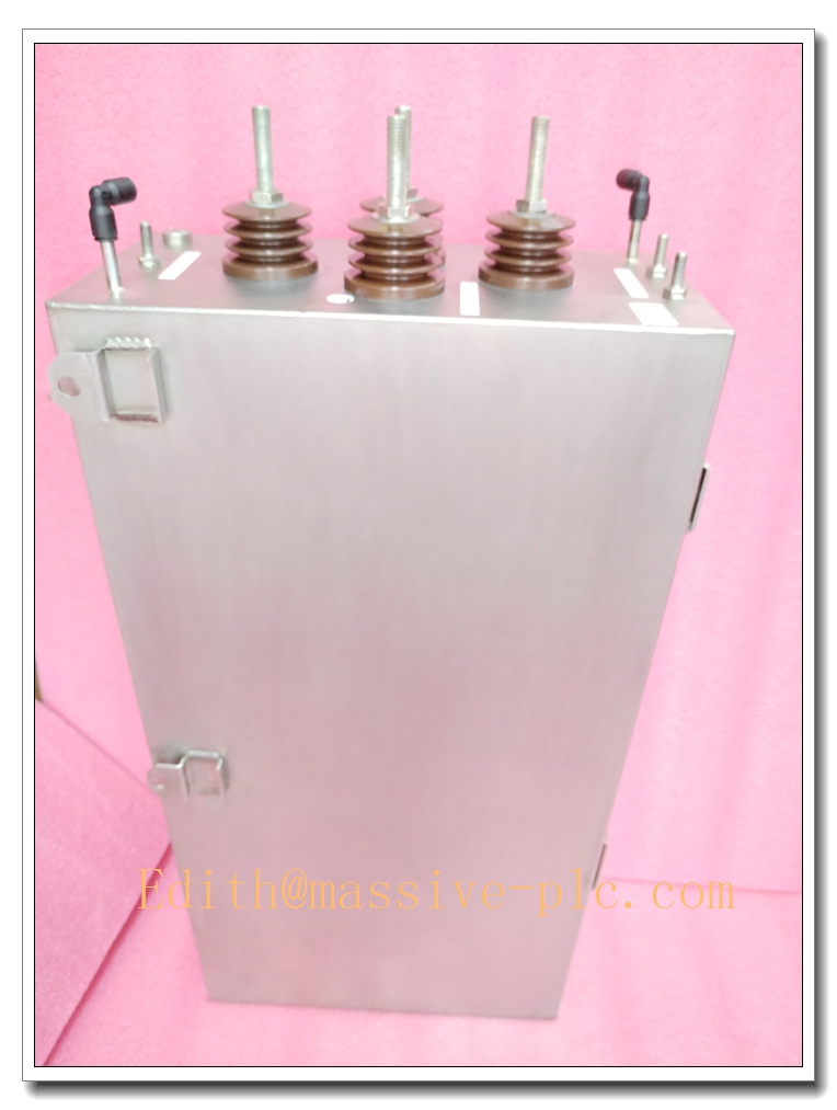
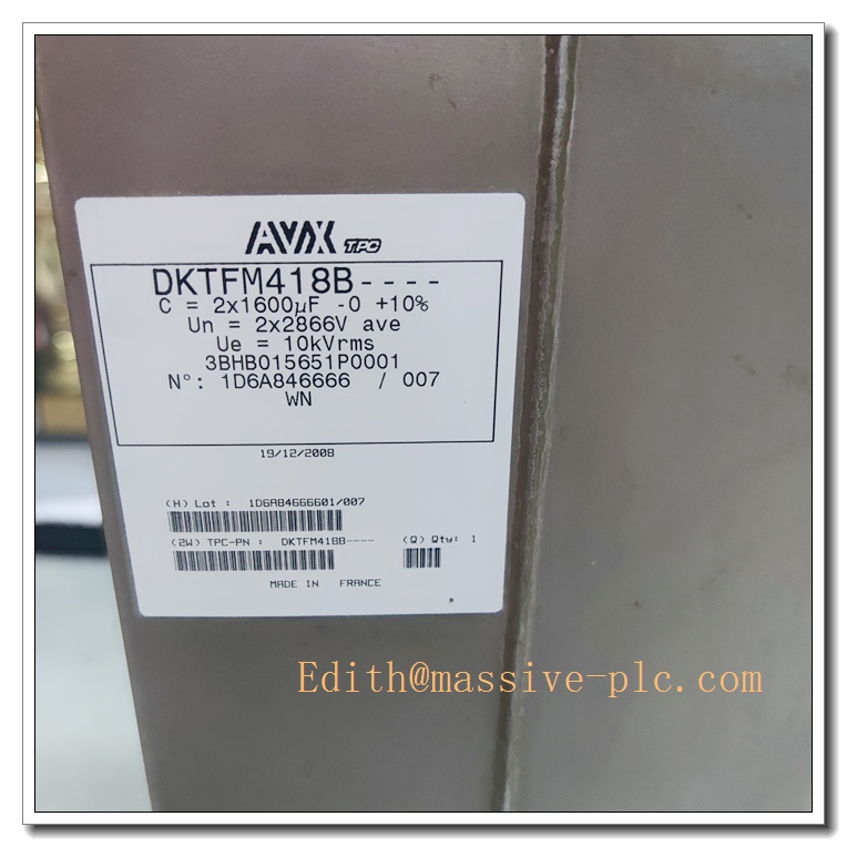
Description
DKTFM418B (3BHB015651P0001) Product Technical Specification & Operation Manual
Product Overview
The DKTFM418B, with part number 3BHB015651P0001, is a high-performance industrial control module developed for automated power and process control systems. Engineered with industrial-grade chip architecture and rigorous electromagnetic compatibility design, this module delivers outstanding stability, anti-interference capability and long-term operational reliability in harsh industrial environments. It serves as a core functional component in distributed control systems (DCS) and power automation equipment, dedicated to precise signal acquisition, data transmission and system logic control. Adhering to international industrial design standards, the module features compact structure, plug-and-play compatibility and low power consumption, meeting continuous and stable operation requirements of industrial production scenarios.
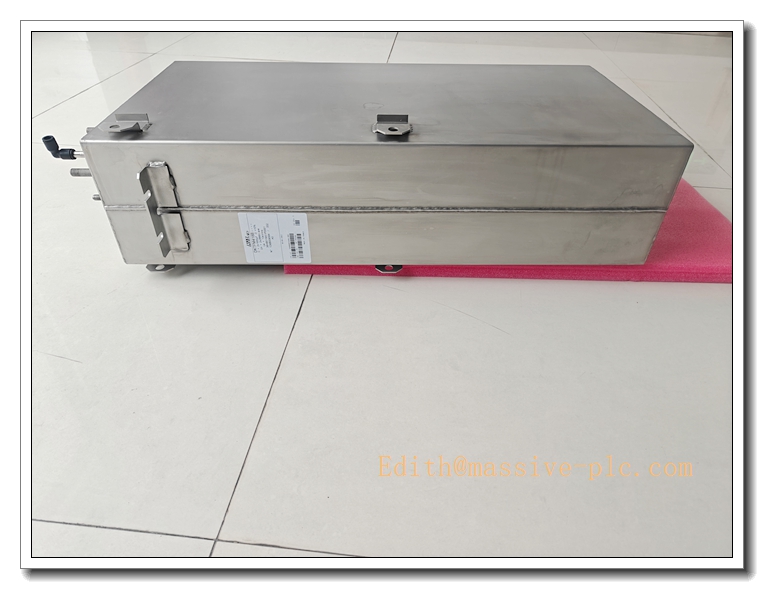
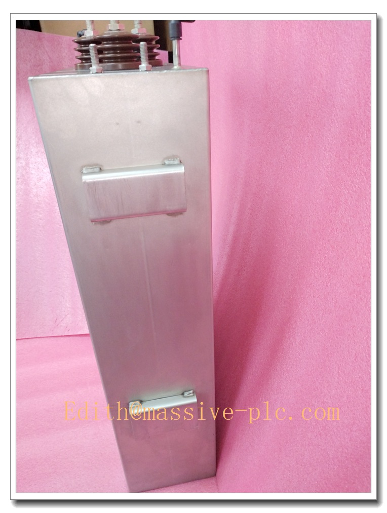
DKTFM418B 3BHB015651P0001
Core Product Highlights
- Industrial-Grade Reliability: Built with high-strength anti-corrosion shell and military-level electronic components, supporting long-term continuous operation under extreme temperature, humidity and electromagnetic interference conditions, with a service life of up to 10 years in industrial scenarios.
- High-Precision Operational Performance: Adopts high-speed data processing chip and optimized signal acquisition algorithm, realizing ultra-low delay signal response and high-accuracy data sampling, effectively avoiding signal distortion and data loss.
- Strong Compatibility & Expandability: Fully compatible with mainstream industrial control system protocols and bus standards, supporting seamless docking with mainstream automation equipment. The modular design reserves expansion interfaces for subsequent system upgrade and function expansion.
- Intelligent Anti-Interference Design: Equipped with multi-level electromagnetic shielding, surge protection and isolation circuit design, effectively resisting industrial frequency interference, static electricity and voltage fluctuation impacts to ensure system stable operation.
- Easy Installation & Maintenance: Standard plug-in structure design, supporting quick disassembly and assembly. Integrated self-diagnosis function can automatically detect module faults and feed back error codes, greatly reducing daily maintenance difficulty and downtime.
- Low Energy Consumption & Energy Saving: Optimized power supply circuit design, with low operating power and no-load loss, reducing long-term system operation energy consumption and operation cost.
Main Technical Specifications
| Technical Parameter | Specification Value |
|---|---|
| Product Model | DKTFM418B, Part No. 3BHB015651P0001 |
| Operating Voltage | DC 24V (Allowable fluctuation range: ±10%) |
| Operating Power | ≤15W |
| Signal Sampling Accuracy | ±0.1% FS |
| Data Response Delay | ≤5ms |
| Operating Temperature Range | -25℃ ~ +70℃ |
| Storage Temperature Range | -40℃ ~ +85℃ |
| Operating Humidity | 5%~95% RH (Non-condensing) |
| Electromagnetic Compatibility | Compliant with IEC 61000-6-2 / IEC 61000-6-4 industrial EMC standards |
| Vibration Resistance | 10~150Hz, 0.15mm amplitude, compliant with IEC 60068-2-6 |
| Communication Protocol | Standard industrial bus protocol, support custom protocol docking |
| Insulation Resistance | ≥100MΩ (DC 500V) |
| Service Life | ≥10 years (Industrial continuous operation environment) |
Recommended Same-Series Models
The DKTFM series industrial control modules cover multi-specification products to meet differentiated demands of different system power, signal acquisition and control scenarios. The recommended same-series compatible models are as follows:
- DKTFM416B (3BHB015650P0001): Low-power basic version, suitable for small-scale industrial automation systems with low signal acquisition demand, featuring lower power consumption and cost-effective performance, ideal for auxiliary equipment control scenarios.
- DKTFM420B (3BHB015652P0001): Enhanced high-precision version, upgraded sampling accuracy and response speed, expanded anti-interference capability, applicable to high-precision process control scenarios such as chemical and pharmaceutical industries.
- DKTFM422B (3BHB015653P0001): Multi-channel extended version, increased signal acquisition and output channels, supporting multi-point synchronous monitoring and control, suitable for large-scale integrated industrial control systems.
- DKTFM418A (3BHB015649P0001): Iterative basic version of DKTFM418B, stable performance, suitable for conventional industrial control renovation and general standard scenarios.
Professional Quality Control & Testing Standard Operating Procedures (SOP)
All DKTFM418B modules strictly implement international industrial quality inspection standards, and complete full-process performance testing and quality verification in accordance with standardized SOP to ensure 100% qualified factory products.
5.1 Pre-Production Component Inspection
All electronic components, shells and connecting accessories are sampled and fully inspected in accordance with IEC industrial component standards. Verify component parameters, durability and compatibility, eliminate unqualified raw materials, and establish component quality files for traceability.
5.2 Semi-Finished Product Aging Test
After module assembly, complete 72-hour continuous power-on aging test under standard industrial temperature and humidity environment. Monitor operating parameters, power consumption and signal stability in real time, screen out products with potential hidden troubles such as unstable operation and signal drift.
5.3 Full Performance Parameter Test
Professional industrial testing equipment is used to test all core parameters including voltage adaptability, signal sampling accuracy, response speed, insulation performance and power consumption. All parameters must fully comply with the technical specification standards, and parameter deviation is strictly prohibited.
5.4 Environmental Adaptability Test
Complete high and low temperature alternating test, humidity resistance test, vibration test and electromagnetic interference test in accordance with IEC 60068 series standards. Simulate extreme industrial working conditions to verify product environmental adaptability and structural stability.
5.5 Finished Product Aging & Factory Inspection
After passing all performance tests, conduct 24-hour finished product secondary aging test. Finally, complete appearance inspection, interface detection and program self-diagnosis test, and only products with full qualified indicators are allowed to be put into storage and delivered.
New Module Installation Guidelines
6.1 Pre-Installation Preparation
- Confirm that the module model and part number are consistent with the demand, check the product appearance for damage, interface for looseness, and accessories for completeness.
- Cut off the power supply of the entire control system and confirm the system is in complete power-off state to avoid electric shock and equipment burnout.
- Clean the installation slot and surrounding dust and sundries to ensure a dry, clean and dust-free installation environment.
- Prepare professional insulating tools and anti-static gloves to avoid static damage to the module circuit board.
6.2 Installation Steps
- Hold the module shell steadily, align the module with the system standard slot, and push it horizontally and slowly until the module is closely fitted with the slot and the locking buckle pops up automatically.
- Fasten the fixed screws on both sides of the module to ensure firm installation without looseness, avoiding vibration displacement during equipment operation.
- Connect the power line and signal line in strict accordance with the wiring diagram, confirm accurate wiring sequence, no short circuit or wrong connection, and fix the wiring terminals.
6.3 Post-Installation Debugging
- After confirming the correct installation and wiring, power on the system slowly, observe the module indicator status, and confirm the power indicator is normally on without alarm prompt.
- Start the system self-diagnosis program to detect module communication status, signal acquisition function and data transmission performance.
- Simulate working condition operation, test module response accuracy and stability, and put it into formal operation after all functions are normal.
DKTFM418B 3BHB015651P0001
Application Scenarios & Product Characteristics
7.1 Core Application Scenarios
- Power Industry Automation: Applied to power distribution control, substation monitoring, wind power and photovoltaic power generation system signal acquisition and logic control, ensuring stable operation of power automation systems.
- Process Industrial Control: Suitable for chemical, petroleum, metallurgy, cement and other process industries, realizing real-time monitoring and precise control of production parameters such as temperature, pressure and flow.
- Intelligent Manufacturing Equipment: Used in automated production lines, CNC equipment, intelligent testing equipment, completing equipment operation signal collection and system collaborative control.
- Building Intelligent Control: Applied to intelligent building power monitoring, environmental monitoring and equipment automatic control systems.
- Water Conservancy & Environmental Protection Monitoring: Used in water quality monitoring, sewage treatment equipment and water conservancy automation control systems, supporting long-term stable outdoor and indoor operation.
7.2 Product Application Characteristics
- Strong Environmental Adaptability: Adapt to high temperature, low temperature, high humidity and multi-dust industrial environments, suitable for indoor and outdoor industrial working conditions.
- Stable & Reliable Operation: Zero failure rate in long-term continuous operation, effectively reducing system downtime and improving production efficiency.
- Easy System Integration: Standard interface and protocol design, convenient for docking with various industrial control systems, low integration cost and short cycle.
- Low Maintenance Cost: Intelligent self-diagnosis function, fast fault location, simple daily maintenance, no frequent component replacement.
Frequently Asked Questions (FAQ)
Q1: The module power indicator is off after power-on, what is the reason and solution?
A1: Possible reasons include abnormal system power supply, wrong wiring or loose module installation. Solutions: Detect whether the system power supply voltage is within the standard range; check whether the power wiring is correct and firm; re-plug and fix the module to ensure complete contact with the slot.
Q2: Module signal acquisition is inaccurate and data fluctuates abnormally
A2: It may be caused by external electromagnetic interference, loose signal wiring or excessive ambient temperature. Solutions: Check and fix signal line terminals; add electromagnetic shielding measures for the equipment; ensure the module operating environment temperature is within the standard range; restart the module for calibration.
Q3: System cannot recognize the module and communication failure occurs
A3: The communication protocol is mismatched or the module program is abnormal. Solutions: Confirm that the system communication protocol is consistent with the module parameter configuration; restart the system and module; re-flash and upgrade the module program if necessary.
Q4: The module alarms after long-term operation
A4: It may be caused by internal dust accumulation, aging circuit or parameter drift. Solutions: Power off and clean the module dust; perform parameter calibration through the system; replace the module if the alarm cannot be eliminated after debugging.
Q5: Can the module be used in high-vibration industrial scenarios?
A5: Yes. The module has passed professional industrial vibration testing, with anti-loosening structural design, which can adapt to conventional industrial vibration scenarios and maintain stable operation.


 Start Chat




