Description
Woodward TG-13 A8516-038/9 Full English Technical Document
Product Title
Woodward TG-13 A8516-038/9 Mechanical-Hydraulic Turbine Speed Governor
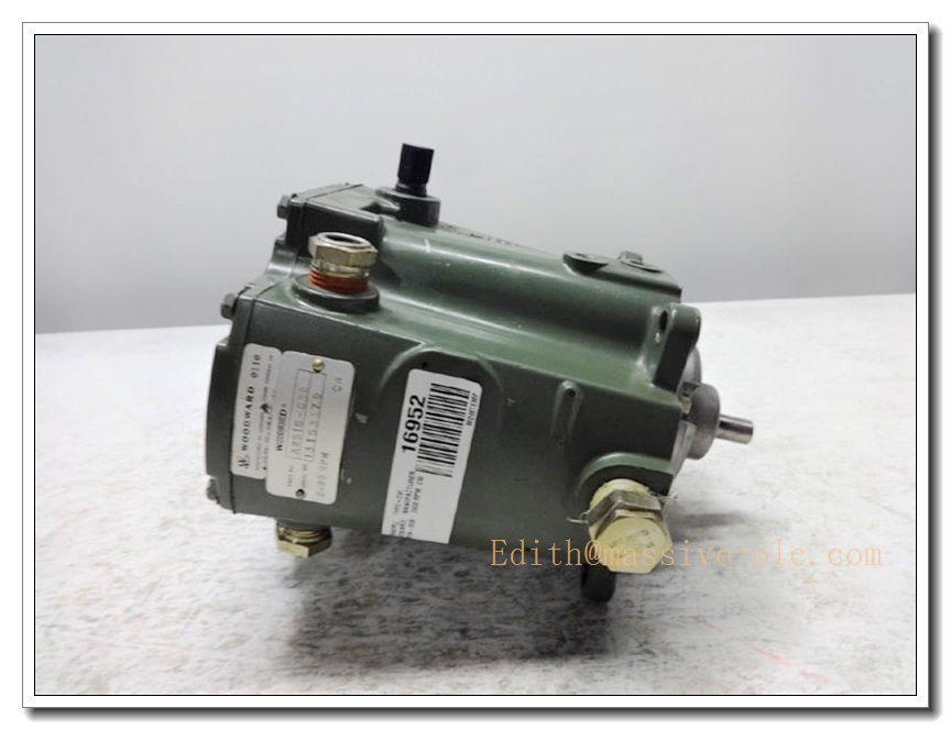
Woodward TG-13 A8516-038/9
Product Description
The Woodward TG-13 A8516-038/9 is a rugged, self-contained mechanical-hydraulic turbine speed governor engineered for precise, reliable speed regulation of industrial steam turbines and associated prime mover equipment. Built on Woodward’s decades of proven hydraulic control technology, this unit integrates a built-in speed sensing ball head assembly, dedicated oil pump, and hydraulic actuation mechanism into a single compact die-cast aluminum housing. It delivers stable droop-based speed control without external hydraulic power sources, making it a field-proven, low-maintenance solution for industrial prime movers operating in harsh, high-vibration environments.
Technical Specifications
- Model Type: TG-13 Mechanical-Hydraulic Turbine Governor
- Part Number: A8516-038/9
- Speed Regulation Range: 1200–2400 RPM
- Rated Speed Droop: 2010 RPM at 2° droop setting
- Output Shaft Torque: 16 N·m (12 ft-lb)
- Drive Shaft Rotation Direction: Counterclockwise
- Construction Material: Die-cast aluminum, fully weatherproof enclosure
- Internal Design: Self-contained sump with integrated speed-sensing ball head and hydraulic oil pump
- Safety Certifications: ATEX, HAZLOC certified for hazardous industrial locations
- Operating Temperature Range: -30°C to +85°C
- Net Weight: Approximately 5.2 kg
- Mean Time Between Failures (MTBF): ≥80000 hours
- Warranty Period: 12 months from factory delivery
Key Features and Advantages
- Fully self-contained design eliminates the need for external hydraulic power supplies or complex auxiliary piping, drastically reducing system integration complexity
- Precision mechanical-hydraulic speed sensing and actuation delivers consistent, drift-free speed regulation performance even under extreme vibration and temperature fluctuation conditions
- 2° standard droop setting supports stable parallel operation of multiple prime movers on a shared grid, perfectly matching industrial generator set load-sharing requirements
- ATEX and HAZLOC hazardous location certification allows safe deployment in oil & gas, petrochemical, and other explosive industrial environments
- Compact die-cast aluminum weatherproof housing provides excellent corrosion resistance, suitable for outdoor or unconditioned turbine hall deployment
- Simple, field-serviceable internal structure minimizes maintenance workload, with widely available spare parts supporting long-term on-site repair without full unit replacement
- Directly compatible with API 611 standard industrial steam turbine interfaces, enabling drop-in replacement for legacy Woodward TG series governors without major mechanical modification
- Integrated overspeed protection interlock logic provides secondary safety protection for the prime mover, preventing catastrophic over-speed damage to turbine equipment
Model Parameter Details
| Part Number | Core Configuration |
|---|---|
| A8516-038/9 | Standard TG-13 mechanical-hydraulic governor, 1200–2400 RPM speed range, 2° droop setting, counterclockwise drive shaft, ATEX/HAZLOC certified, full self-contained hydraulic system |
Application Fields
- Industrial steam turbine speed control for small and medium-sized power generation units
- Oil & gas industry centrifugal compressor and pump prime mover speed regulation
- Petrochemical plant turboexpander precise speed control
- Industrial draft fan and large blower prime mover speed stabilization
- Offshore platform independent power generation unit turbine control
- Legacy industrial turbine control system retrofitting and governor replacement scenarios
Related Product Recommendations
- Woodward TG-17 Extended Speed Range Mechanical Hydraulic Governor
- Woodward 9907-162 Digital Speed Control Module
- Woodward TG Series Governor Dedicated Hydraulic Oil Filter Kit
- Woodward 8272-582 Manual Speed Setting Potentiometer Unit
- Woodward ProTech-GII Digital Overspeed Protection System
- Woodward TG Series Governor Special Mounting Adapter Bracket
- Woodward 505 Digital Steam Turbine Controller
- Woodward TG Series Governor Field Calibration Toolkit
Pre-Installation Safety Precaution
Before initiating any hardware installation or commissioning procedures, ensure all connected turbine prime mover systems are fully locked out, tagged, and isolated from steam, fuel, and power sources in strict compliance with local industrial safety regulations. Only qualified turbine control and mechanical maintenance personnel with professional high-pressure operation certification are authorized to perform installation work. Never disassemble the internal hydraulic calibration components of the governor without official Woodward authorization, as this may permanently damage the unit’s precision speed regulation performance and invalidate safety certifications.
Hardware Installation Steps
- Select a dedicated rigid mounting position on the turbine gearbox or designated control panel, ensuring sufficient clearance for drive shaft connection and maintenance access, avoiding direct exposure to high-temperature steam radiation or corrosive fluid splashes
- Secure the governor firmly to the mounting base using the included high-strength mounting bolts, confirming no mechanical looseness that could cause vibration-induced misalignment during long-term operation
- Align the governor drive shaft perfectly with the turbine output shaft, install the dedicated flexible coupling, and verify the counterclockwise rotation direction matches the unit’s specification
- Connect the governor’s oil sump ventilation pipe and any required external oil return lines, ensuring all piping connections are leak-free and free of internal debris
- Wire all external control signal circuits (manual speed adjustment, emergency trip interlock) strictly following the official Woodward wiring schematic, confirming all interlock safety loops are correctly configured
- Torque all mounting bolts and piping connections to the specified torque values, then fill the governor’s internal sump with the recommended grade of hydraulic oil to the designated level
System Configuration Workflow
- Perform a full pre-commissioning inspection of all mechanical and piping connections, confirming no leaks or misalignment issues before rotating the turbine shaft manually
- Connect the official Woodward TG series calibration tool to the governor’s adjustment access port, establish stable communication with the unit
- Complete basic parameter setup, including rated speed configuration, droop value calibration, and overspeed trip threshold setting
- Perform no-load speed regulation testing, adjusting the internal hydraulic gain to ensure smooth, stable speed response without hunting or overshoot
- Configure external interlock logic, verifying emergency trip signal input can trigger immediate governor valve closure as designed
- Save all calibrated parameters to the unit’s internal mechanical setting, then seal the calibration access cover with the official tamper-proof tag as required by local industrial safety rules
Post-Installation Verification Checklist
- Confirm the governor’s internal oil pressure and sump oil level operate within the normal specified range, with no persistent oil leaks or abnormal noise during operation
- Validate that no-load speed regulation accuracy and stability fully meet the turbine design specifications, with no visible speed hunting or fluctuation
- Perform full-load step response testing, confirming the unit maintains stable speed control under sudden load change conditions
- Test the emergency trip function manually, confirming the governor can fully close the turbine control valve within the specified response time
- Verify interconnection compatibility with the turbine’s existing control system, confirming seamless signal exchange and coordinated operation
- Trigger the built-in overspeed test routine, confirming the governor’s secondary overspeed protection interlock triggers at the pre-set threshold as designed