Description
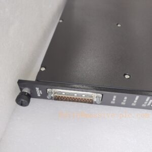
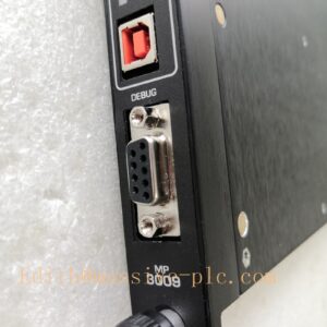
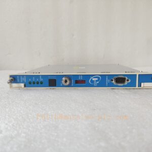
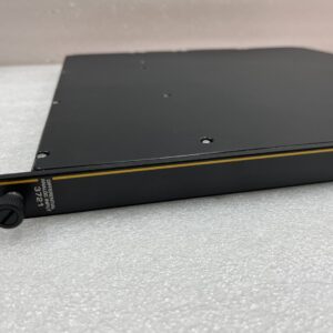
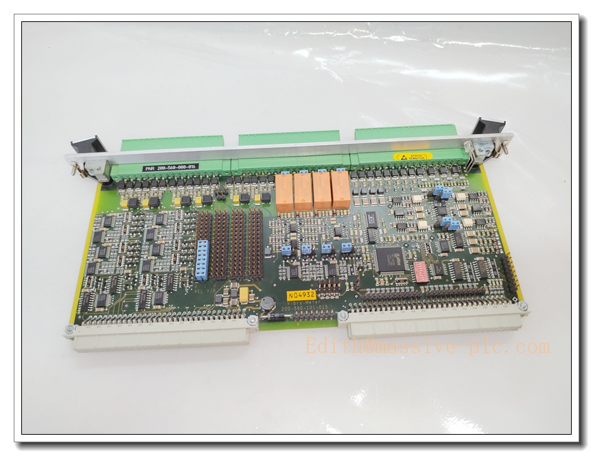
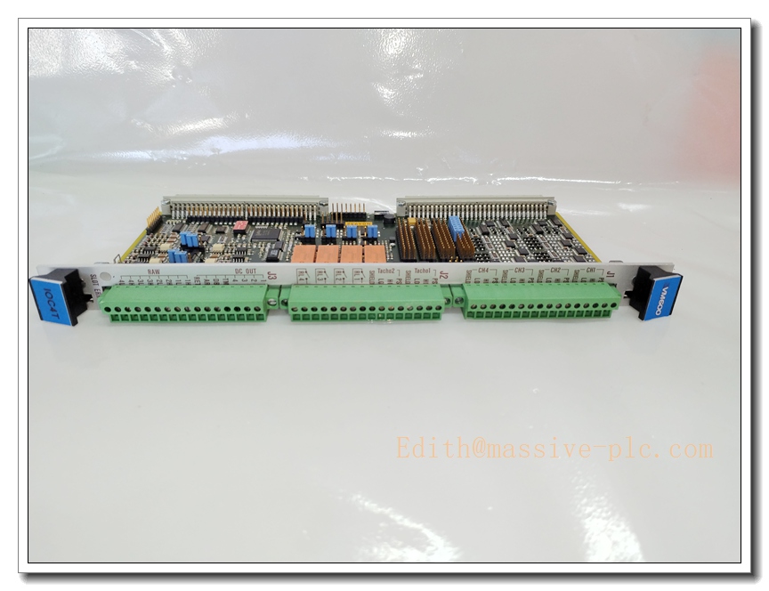
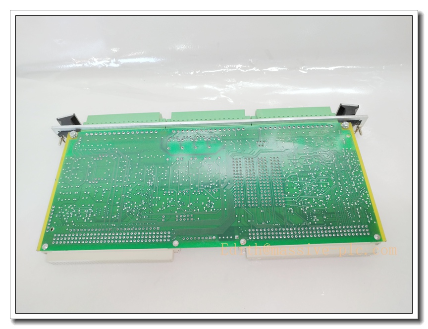
Vibro-Meter (Meggitt) VM600 IOC4T 200-560-000-11 Rear I/O Interface Card
Product Title
Vibro-Meter VM600 IOC4T 200-560-000-11 | Rear Rack I/O Terminal Interface Card, Paired with MPC4 Machinery Protection Card for VM600 ABE04x Rack
Product Description
The IOC4T 200-560-000-11 is the rear-mounted I/O terminal interface card exclusively designed to work together with the front MPC4 DSP machinery protection card inside VM600 ABE04x 6U rack. It is installed in the rear cage, directly behind the MPC4 in the same rack slot. It provides screw terminal blocks for field wiring of proximity probes, IEPE accelerometers, velocity transducers, tacho/phase signals, 4-20mA analog outputs and relay alarm signals. It routes raw sensor signals from field measurement chains to MPC4 for digital processing, and transmits processed analog and alarm outputs from MPC4 to external DCS/SCADA systems. It integrates surge and EMC protection for all field wiring circuits. The IOC4T reports wiring faults and channel diagnostics back to the MPC4 and VM600 CPUM. This card is a mandatory matching pair for , widely used for API670 turbomachinery protection, SIL2 certified machinery monitoring systems.
Technical Specifications
| Item | Parameter |
|---|---|
| Brand | Vibro-Meter (Meggitt / Baker Hughes) |
| Model | VM600 IOC4T, Part No. 200-560-000-11 |
| Module Type | Rear I/O Terminal & Signal Interface Card |
| Form Factor | 6U rear card, mounted in rack rear cage |
| Pairing | Works exclusively with front card in same slot |
| Input Terminals | 4 dynamic sensor inputs + 2 tacho / phase reference inputs |
| Output Terminals | 4 × configurable analog outputs (0–10V or 4–20mA); relay alarm/trip signal terminals |
| Signal Protection | Built-in surge, ESD and EMI protection for field wiring |
| Connector | Removable screw terminal blocks for field cables |
| Rack Bus | proprietary internal bus communicating with |
| Power Source | Powered by rack backplane via RPS6U power supply |
| Operating Temperature | -25°C ~ +65°C |
| Storage Temperature | -40°C ~ +85°C |
| Humidity | 5%–95% non-condensing |
| Vibration | IEC 60068-2-6 |
| Shock | IEC 60068-2-27 |
| Certification | SIL2 compatible, CE, API670 compliant |
| Enclosure Rating | IP20 (rear rack housing) |
| Weight | Approx. 0.85kg |
| Diagnostics | Cable break, short circuit, sensor fault, terminal wiring error |
Compatibility & Installation Pitfalls
Compatibility
- Host Rack: ABE041 / ABE042 6U rack
- Mandatory Front Pair: front card (200-510-071-11) in the identical slot
- Rack CPU: CPUM 200-595-100-01
- Rack Power: RPS6U 200-582-500
- Signal Isolator: GSI127 244-127-000-017-A2-B galvanic separation unit
- Sensors: Eddy current probes, IEPE accelerometers, velocity pickups, tachometer sensors
- Software: RPS / MPS engineering software, VibroSight
- Not compatible: IOC16T, generic VME racks, non- backplanes, mismatched firmware revisions
Critical Installation Pitfalls
- Slot pairing rule: IOC4T must be installed directly behind the corresponding card. Cross-slot pairing will cause total signal loss and protection failure.
- Firmware consistency: firmware revision must match and CPUM firmware. Mismatched firmware leads to channel communication failure, missing measurements and incorrect alarm logic.
- Terminal torque control: Over-tightening damages terminal block pins; loose terminals create high contact resistance, signal drift and intermittent vibration readings.
- Shield grounding: Field sensor cables must use shielded twisted pair, single-point grounding. Dual-point grounding creates ground loops and high noise in dynamic vibration signals.
- Analog output configuration: 4-20mA / 0-10V must be selected in RPS software before commissioning. Wrong setting causes incorrect value sent to DCS.
- Surge protection requirement: For long field cables or hazardous areas, add external surge protection and GSI127 galvanic isolator to protect inputs.
- No independent hot-swap: cannot be hot swapped separately. The whole + pair maintenance requires protection bypass before pulling out the front .
Standard Operating Procedure (SOP)
- Pre-Install Inspection & LOTO Perform lock-out tag-out for all field sensor wiring. Inspect PCB, terminal blocks and rear connectors for damage. Verify part number and firmware match and rack BOM.
- Rear Cage Installation Insert card into the rear cage slot matching the front card. Fully seat rear backplane connectors and fasten the card locking screws.
- Field Sensor Wiring Wire vibration probes, accelerometers and tacho sensors to screw terminals. Wire analog 4-20mA and relay trip outputs to DCS/PLC. Use shielded twisted pair, perform continuity and insulation test.
- Open RPS engineering software, configure + hardware pair, define sensor types, analog output mode and relay alarm assignment. Download configuration to CPUM.
- Power-Up & Commissioning Energize rack power. Complete self-test. Inject calibration signals to verify sensor reading, analog output and relay alarm/trip action.
- Runtime Operation & Diagnostics Monitor channel status, wiring faults and diagnostic alarms via VibroSight or plant HMI. Carry out periodic proof tests for SIL audit.
- Replacement Procedure Activate protection bypass for the measurement channels. Power down rack (or perform hot-swap workflow). Disconnect field terminals, remove old . Install spare , rewire terminals, restore power and validate all measurement and protection functions.
Application Scenarios
- Steam / Gas Turbine API670 Machinery Protection
- Centrifugal Compressor Vibration & Shaft Displacement Monitoring
- Generator rotor dynamic monitoring
- Critical pump, fan and expander safety protection
- Petrochemical turbomachinery monitoring cabinets
- Power plant rotating equipment supervision
- system retrofit and spare parts replacement
Supporting Components
- ABE04x 6U Rack
- 200-510-071-11 front machinery protection card
- CPUM 200-595-100-01 CPU module
- RPS6U 200-582-500 rack power supply
- GSI127 244-127-000-017-A2-B galvanic separation unit
- Eddy current probes / IEPE accelerometers / tacho sensors
- RPS / MPS configuration software
- Shielded twisted pair sensor cables
- Signal calibrator for loop commissioning
- Spare removable terminal blocks
Related Model Recommendations (10 Models)
- 200-510-071-11: Matching front machinery protection card
- CPUM 200-595-100-01: rack CPU
- RPS6U 200-582-500: Rack power supply
- IOC16T 200-565-000-013: 16-channel analog rear I/O card
- IRC4: relay trip output module
- AMC8: Analog measurement front card
- GSI127 244-127-000-017-A2-B: Galvanic isolator
- XMV16: High density condition monitoring front card
- IQS9xx: Eddy current signal conditioner
- CA-series IEPE accelerometer