Description
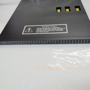
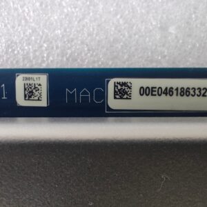
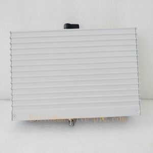
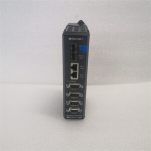
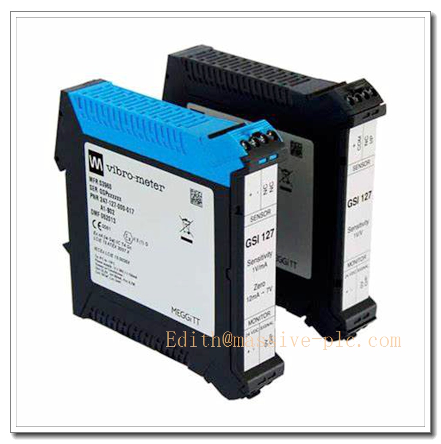
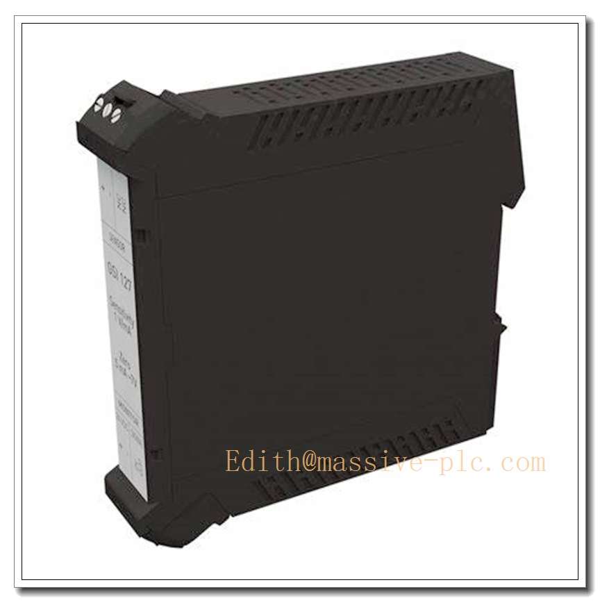
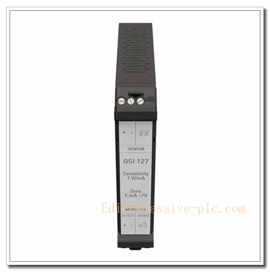
Vibro-Meter (Meggitt) GSI127 244-127-000-017-A2-B Galvanic Separation Unit
Product Title
Vibro-Meter GSI127 244-127-000-017-A2-B | DIN-Rail Galvanic Isolation / Galvanic Separation Unit for VM600 Machinery Protection & Vibration Sensor Signal Chains
Product Description
The GSI127 (244-127-000-017-A2-B) is a high-performance galvanic separation unit manufactured by Vibro-Meter (Meggitt Sensing Systems). It provides 4kV galvanic isolation between field sensors and VM600 rack monitoring I/O modules, eliminating ground loops and suppressing common-mode noise for vibration, dynamic pressure and proximity measurement signals. It can supply power to field-side signal conditioners up to 21mA and supports both voltage-to-voltage and current-to-voltage signal transmission for long-distance high-frequency AC measurement links. This unit is designed for hazardous area applications, with intrinsic safety protection, widely paired with IEPE accelerometers, eddy current proximity probes and IPC707/IQS9xx signal conditioners for turbomachinery protection systems, fully compatible with VM600 MPS/CMS rack system.
Technical Specifications
| Item | Parameter |
|---|---|
| Brand | Vibro-Meter (Meggitt Sensing Systems) |
| Model | GSI127, Part No. 244-127-000-017-A2-B |
| Module Type | Galvanic Separation Unit (Signal Isolator) |
| Mounting | DIN rail mounting |
| Galvanic Isolation | 4kV RMS (Sensor ↔ Monitor); 50V RMS (Power ↔ Output) |
| Bandwidth | DC ~ 20kHz (±0.5dB), -3dB @ 30kHz typical |
| Frame Voltage Rejection | ≥60dB (10–400Hz); ≥30dB (400Hz~100kHz) |
| Input Signal Range | 0~20VDC |
| Output Signal Range | 0~20VDC, for ≥10kΩ load |
| Power Supply | 18~30VDC (24VDC nominal, ±25%) |
| Power Consumption | ≤120mA @ 20mA sensor load |
| Max Sensor Side Supply Current | 21mA |
| Linearity Error | <0.5% (-46dB) DC~20kHz |
| Operating Temperature | -30°C ~ +65°C |
| Storage Temperature | -40°C ~ +85°C |
| Humidity | 5%~95% non-condensing |
| Vibration Resistance | IEC 60068-2-6, 2g peak |
| Enclosure Rating | IP20 |
| Weight | Approx. 320 g |
| Terminals | Removable screw terminal connectors |
| Certification | IECEx, ATEX, SIL2 compatible for machinery protection chains |
Compatibility & Installation Pitfalls
Compatibility
- System: VM600 MPS / CMS machinery protection rack
- VM600 I/O Cards: MPC4, IOC4T, IOC16T, AMC8
- Field Sensors & Conditioners: CA-series IEPE accelerometers, CP dynamic pressure sensors, TQ eddy-current probes, IPC707, IQS9xx signal conditioners
- Configuration Software: VM600 RPS engineering software
- Mounting: Standard 35mm DIN rail inside control cabinet
- Not compatible: Non-Vibro-Meter proprietary vibration systems, signal chains exceeding 21mA sensor draw
Critical Installation Traps
- Current limit of sensor side: Max 21mA sensor supply current. If signal conditioner consumption exceeds this value, the GSI127 will stop working and cause signal loss.
- Grounding principle: The purpose of GSI127 is to break ground loops. Do NOT connect both sensor side and monitor side shields to protective earth simultaneously; single-point grounding is mandatory.
- Wiring bandwidth impact: High-frequency vibration signals require shielded twisted pair cable. Long cable with poor shielding will reduce high-frequency performance and introduce noise.
- DIN rail mechanical fixation: Ensure firm clip mounting. Loose mounting under vibration can cause intermittent terminal contact and unstable vibration readings.
- Terminal torque: Improper screw torque leads to high contact resistance, signal drift or thermal heating. Do not over-tighten the removable terminals.
- Hazardous area installation: For Ex applications, strictly follow IECEx/ATEX installation rules. Wrong wiring can void intrinsic safety certification.
- No hot-swap for signal loop: While itself can be removed from DIN rail, removing it during running machinery will break vibration measurement and may trigger machine protection trips.
Standard Operating Procedure (SOP)
- Pre-Install Inspection & LOTO Lock-out tag-out for sensor signal and 24VDC power circuit. Inspect housing and terminal blocks for damage. Verify model code A2-B matches measurement chain requirement.
- DIN Rail Mounting Snap onto 35mm standard DIN rail inside cabinet, confirm locking clip is fully engaged.
- Field & Monitor Side Wiring Wire sensor/conditioner to input terminals; wire output terminals to IOC4T / MPC4 card. Use shielded twisted pair, implement single-point shield grounding. Torque terminals to specified value. Continuity test before power-up.
- Open RPS software, configure measurement chain as galvanic isolation type, select voltage or current transfer function according to sensor type.
- Power-Up and Commissioning Energize 24VDC supply. Inject test signal at sensor side. Verify clean, accurate vibration signal received on channel, check noise floor and frequency response.
- Runtime Operation & Diagnostics Monitor vibration signal quality via HMI or VibroSight. Periodically check for signal dropout or noise increase during routine proof tests.
- Replacement Procedure LOTO the 24VDC power and sensor signal. Disconnect screw terminals, release DIN rail clip and remove faulty unit. Install spare , rewire terminals, restore power and re-calibrate measurement chain.
Application Scenarios
- Steam / Gas Turbine Vibration & Dynamic Pressure Monitoring
- Centrifugal Compressor Machinery Protection (API670)
- Generator rotor vibration measurement
- Pump, fan and critical rotating equipment condition monitoring
- Petrochemical & power plant hazardous zone vibration sensor interfaces
- Offshore turbomachinery safety monitoring
- system retrofit & spare part replacement for existing measurement chains
Supporting Components
- 35mm standard DIN rail
- Shielded twisted pair signal cables
- Regulated 24VDC power supply
- MPC4 / IOC4T rack module
- IPC707 / IQS9xx signal conditioner
- CA / CP / TQ series Vibro-Meter sensors
- RPS configuration software
- Removable spare terminal blocks
- Multimeter & signal calibrator for loop test
- Cabinet cable glands and cable ties
Related Model Recommendations (10 Models)
- 244-127-000-011: Alternate variant
- CPUM 200-595-100-01: rack CPU
- MPC4 200-510-071-113: vibration protection card
- IOC4T 200-560-000-113: Rear I/O communication card
- IOC16T 200-565-000-013: 16-channel analog input
- IRC4: relay trip output module
- RPS6U 200-528-500-013: rack power supply
- AMC8: analog measurement card
- XMV16: high density condition monitoring module
- IQS9xx: Eddy current signal conditioner for proximity probes