
Description
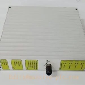
TRICONEX 5361S2 Digital Output Module
Product Overview
The TRICONEX 5361S2 is a Triple Modular Redundant (TMR) digital output module belonging to Tricon 5000‑series SIS platform. Adopting three‑channel hardware voting architecture, it converts internal safety logic commands into discrete 24 VDC field drive signals for solenoid valves, trip relays and safety actuators. The S2 hardware revision delivers enhanced diagnostic coverage and improved noise immunity. It meets IEC 61508 SIL 3 safety integrity for safety‑critical interlock loops in process industries.
Typical Applications
- ESD Emergency Shutdown System: Drive shutdown solenoid valves and trip relays for refinery, petrochemical plant safety interlock loops.
- BMS Burner Management System: Control fuel‑gas solenoid valves, ignition relays and burner safety cut‑off devices.
- Fire & Gas Safety System: Trigger fire suppression and gas‑isolation safety actuators upon hazard detection.
- Turbine & Compressor Protection: Execute turbine trip output and auxiliary safety relay drive for power‑generation facilities.
- Off‑shore & On‑shore Oil‑gas Facilities: Safety valve actuation for pipeline and platform SIS cabinets.
- Chemical Process Safety: Control reactor emergency shutdown relays and safety isolation devices.
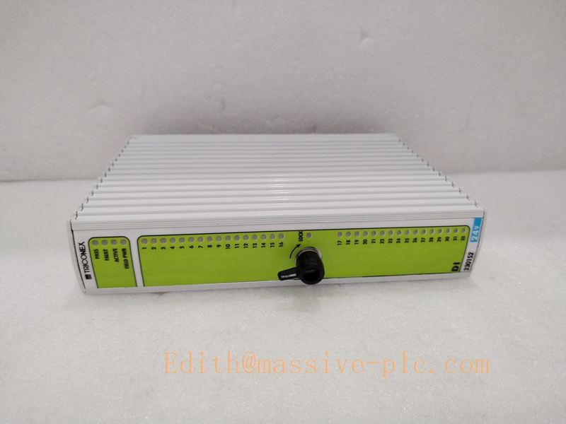
TRICONEX 3301S2
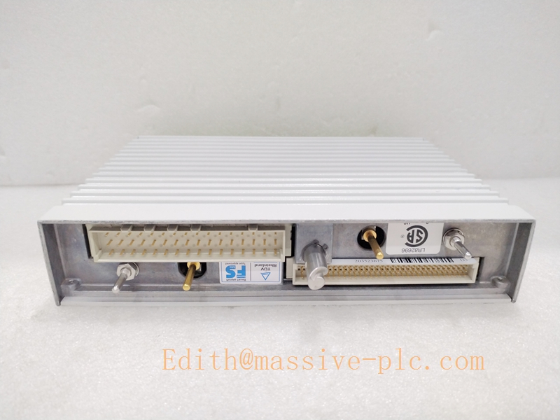
TRICONEX 3301S2
Technical Specifications
| Item | Parameter |
|---|---|
| Model | 5361S2 |
| Module Type | TMR Digital Output Module (S2 Revision) |
| Channel Count | 16 digital output channels |
| Output Type | Sink / Source selectable, 24 VDC nominal |
| Operating Voltage | 18‑30 VDC field supply |
| Max Channel Current | 1 A per channel |
| Total Module Max Current | 8 A aggregate |
| Architecture | Triple Modular Redundant (TMR), 2‑out‑of‑3 hardware voting |
| Safety Certification | SIL 3 compliant per IEC 61508 |
| Backplane Bus | TriBus high‑speed proprietary bus |
| Isolation | 1500 V channel‑to‑backplane galvanic isolation |
| Diagnostics | Load monitoring, open‑circuit, short‑circuit detection |
| Operating Temperature | 0 °C ~ +60 °C |
| Storage Temperature | ‑40 °C ~ +85 °C |
| Humidity | 5 %‑95 % RH, non‑condensing |
| Compatibility | Tricon 5000‑series main chassis; matched 4000‑series termination cable assemblies |
| Net Weight | 1.45 kg |
| Installation Environment | Cabinet‑only mounting, IP20 |
Key Features
- TMR 2‑out‑of‑3 Voting Architecture: Three independent internal output circuits perform hardware voting. Single‑path hardware fault will not cause unsafe output state, maintaining safety‑loop continuity.
- Enhanced S2 Hardware Revision: Improved circuit design provides higher diagnostic coverage and stronger EMI rejection compared to original 5361 version.
- Comprehensive Channel Diagnostics: Continuously detect open‑load, short‑circuit and internal hardware faults; fault status indicated via front‑panel LED and reported to Tricon engineering software.
- Hot‑Swap Support: Online module replacement without SIS system shutdown, minimizes plant maintenance downtime.
- Configurable Fail‑safe State: Each channel supports configurable fail‑safe state (de‑energize / energize) upon module fault to satisfy different process safety requirements.
- Galvanic Isolation Design: 1500 V isolation between field side and system backplane, eliminates ground‑loop interference and protects internal SIS circuits.
- Mechanical Anti‑misplug Keying: Physical slot key prevents wrong‑module insertion, avoids hardware damage caused by mis‑installation.
- Seamless 5000‑series Integration: Communicates with main processor via TriBus backplane; channel configuration, fault threshold and output logic can be set within TriStation engineering tool.
Installation Guidelines
- Pre‑installation Inspection: Verify part number and hardware revision; inspect module housing, connectors and pins for physical damage. Follow strict ESD anti‑static handling procedures.
- Chassis Slot Mounting: Insert 5361S2 module into designated I/O slot of Tricon 5000‑series chassis, lock front mounting latch securely. Confirm slot assignment matches system hardware configuration.
- Termination Cable Connection: Connect rear module connector to factory‑pre‑fabricated Tricon termination cable assembly. Use qualified matching harness for field‑device wiring.
- Field Wiring Practice: Route field solenoid valves and relay wiring to termination assemblies. Separate safety signal cables from high‑power motor / VFD cables to reduce EMI coupling. Avoid excessive cable tension and sharp bending.
- Configuration & Commissioning: Set channel output mode, fail‑safe status and diagnostic parameters in TriStation software. Perform loop function test to verify actuation of field safety devices before SIS online operation.
- Environmental Requirements: Install inside indoor control cabinet; avoid moisture, corrosive gas and direct sunlight; keep operating temperature within 0 °C ~ +60 °C.
- Hot‑swap Operation: Unlock front latch and slide out faulty module; insert replacement module and lock latch. The Tricon system will auto‑recognize the hardware without power‑cycle.
Related Inter‑operable Series Models
- 5361: Non‑S2 original‑revision digital output module
- 5351S2: Tricon 5000‑series S2‑revision digital input counterpart module
- 5481S2: Analog output S2 module for Tricon 5000 platform
- 4000187‑320: Matching termination assembly for 5361S2
- 5301S2: Main processor module for Tricon 5000‑series SIS chassis


 Start Chat




