
Description
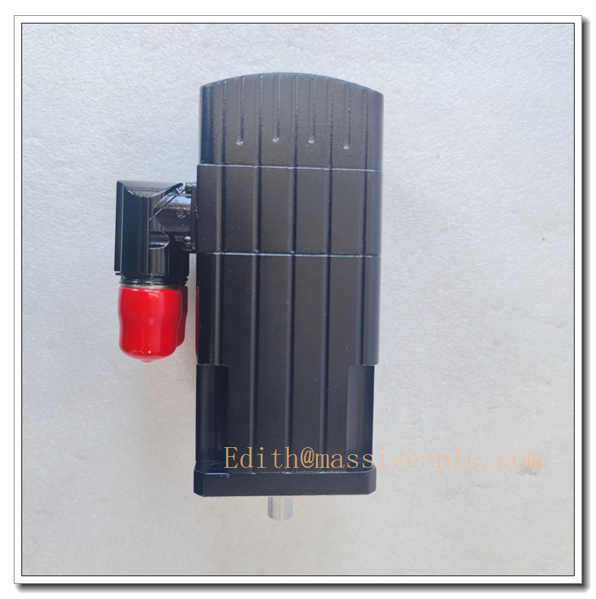
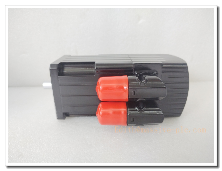
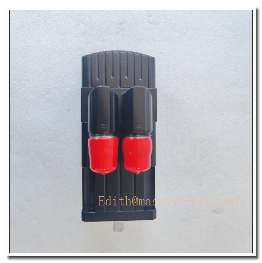
Moog G403-552A Three-Stage Electro-Hydraulic Servo Valve
Product Description
The Moog G403-552A is a high-response three-stage electro-hydraulic servo valve designed for precision closed-loop hydraulic control. It converts low-power ±10 VDC analog command signals into accurately modulated high-pressure hydraulic flow to control actuator position, velocity and force. Built with hardened zero-lapped spool and sleeve construction, this servo valve delivers high dynamic response, low hysteresis and excellent repeatability under continuous heavy-duty cycles. It incorporates an integral pilot stage, main spool and built-in LVDT spool position feedback, enabling stable high-flow regulation for high-performance test rigs and critical industrial motion systems. Engineered to aerospace-grade standards, it serves as a critical spare component for structural test, fatigue test and large force control applications.
G403-552A
Technical Specifications
| Item | Parameter |
|---|---|
| Model | G403-552A |
| Brand | Moog Inc. |
| Valve Type | Three-stage electro-hydraulic servo valve |
| Control Input Signal | ±10 VDC differential analog |
| Rated Flow | 55 gpm (208 L/min) at ΔP=1000 psi (70 bar) across main spool |
| Max Working Pressure | 3000 psi (210 bar) |
| Frequency Response | ≥80 Hz at -90° phase lag, no-load condition |
| Hysteresis | <1.5% of rated flow (typical) |
| Spool Construction | Zero-lapped, hardened stainless steel with anti-wear coating |
| Feedback | Integrated LVDT for main spool closed-loop position feedback |
| Operating Fluid | ISO VG mineral hydraulic oil, fire-resistant fluid compatible upon specification |
| Fluid Temperature Range | 20°C ~ 65°C |
| Operating Ambient Temperature | -20°C ~ +70°C |
| Storage Temperature | -40°C ~ +85°C |
| Mounting | ISO standard manifold mounting pattern |
| Filter Requirement | 3 μm or finer pressure-side filtration |
Compatibility & Installation Traps
Compatibility
- Designed to pair with Moog servo controllers or analog closed-loop hydraulic control systems supporting ±10 V command and LVDT feedback.
- Requires matched hydraulic manifold conforming to the valve’s ISO mounting pattern.
- Must use hydraulic fluid and filtration grade specified in Moog service manual; fluid viscosity and cleanliness directly affect stability.
- Not interchangeable with two-stage Moog servo valves or other three-stage variants; manifold porting, feedback wiring and gain tuning differ.
Common Installation Traps
- Poor hydraulic fluid cleanliness; contamination and particles cause spool sticking, drift and premature valve failure.
- Mismatched manifold porting or uneven mounting torque, leading to external leakage and unstable pressure supply.
- Reversed LVDT feedback wiring; inverted feedback makes the control loop unstable and causes violent actuator runaway.
- Using unshielded command signal cables; EMI noise creates jitter, flow oscillation and poor setpoint tracking.
- Exceeding the 3000 psi working pressure rating, which risks seal extrusion and permanent spool damage.
- Skipping pre-filtering and flushing of the hydraulic manifold before commissioning; residual machining debris damages internal stages.
- Hot installation while the hydraulic system remains pressurized; high-pressure fluid injection hazard and spool impact damage.
- Retaining old controller gain values after valve replacement; improper loop tuning leads to hunting, overshoot or slow response.
Standard Operating Procedure (SOP)
- Pre-inspection: Inspect G403-552A for body scratches, seal damage, deformed electrical connectors and port contamination. Confirm part number and revision match the original valve.
- Lockout and isolation: De-energize the servo controller, shut down the hydraulic power unit, relieve all line pressure and verify zero pressure at manifold ports.
- Cleanroom preparation: Perform work in a clean environment; wear lint-free gloves and protect all ports with protective caps until installation.
- Valve removal: Tag command, LVDT feedback and power wiring. Loosen manifold bolts in a diagonal sequence and lift the old servo valve away from the manifold.
- Mount new valve: Fit new sealing gaskets, align the valve with manifold ports and torque mounting bolts evenly following Moog cross-torque sequence.
- Electrical reconnection: Reconnect shielded analog command cable and LVDT feedback wiring per wiring diagram; separate signal cables from high-power hydraulic motor cables.
- System flushing and leak check: Run manifold flushing cycle, inspect all sealing interfaces for external leakage, confirm filter condition and fluid cleanliness.
- Power-up and loop tuning: Enable hydraulic supply and controller power, run LVDT offset calibration, adjust loop gain and stability margins, perform low-stroke functional test.
- Final commissioning: Execute full-range actuator test, record tuned control parameters, clear fault logs and release the system for test operation.
G403-552A
Application Scenarios
- Structural and aerospace component fatigue test rigs
- Large force material testing machines
- Seismic simulation and multi-axis shake tables
- Heavy-duty industrial force and position closed-loop control
- Automotive durability and crash simulation test benches
- Marine hydraulic actuator high-precision control systems
- Power generation equipment load testing platforms
- Advanced material research servo-hydraulic test systems
Matching Components
- Moog analog servo controller with LVDT feedback interface
- Hydraulic power unit with pressure regulation and 3 μm filtration
- ISO standard mounting manifold and spare seal gasket kit
- Shielded twisted-pair analog signal and LVDT feedback cables
- Hydraulic fluid sampling kit and particle counter
- Torque wrench set for manifold mounting
- Servo tuning software and data acquisition workstation
- Pressure transducers and safety relief valve assemblies
Recommended Related Models (8)
- G403-550A
- G403-551A
- G403-553A
- G403-554A
- G403-555A
- G403-556A
- G403-557A
- G404-601A


 Start Chat




