
Description
Motorola MVME2432 6U VME64 Single-Board Computer
Product Description
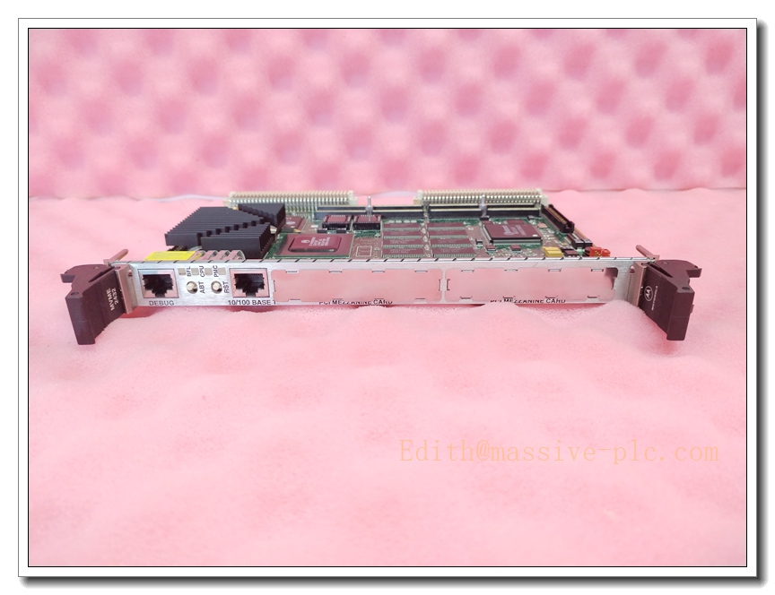
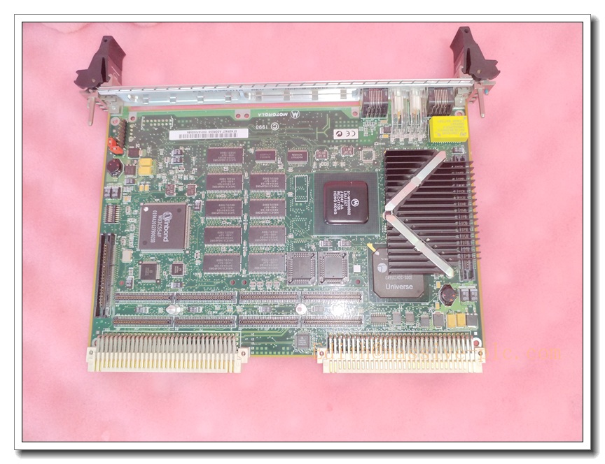
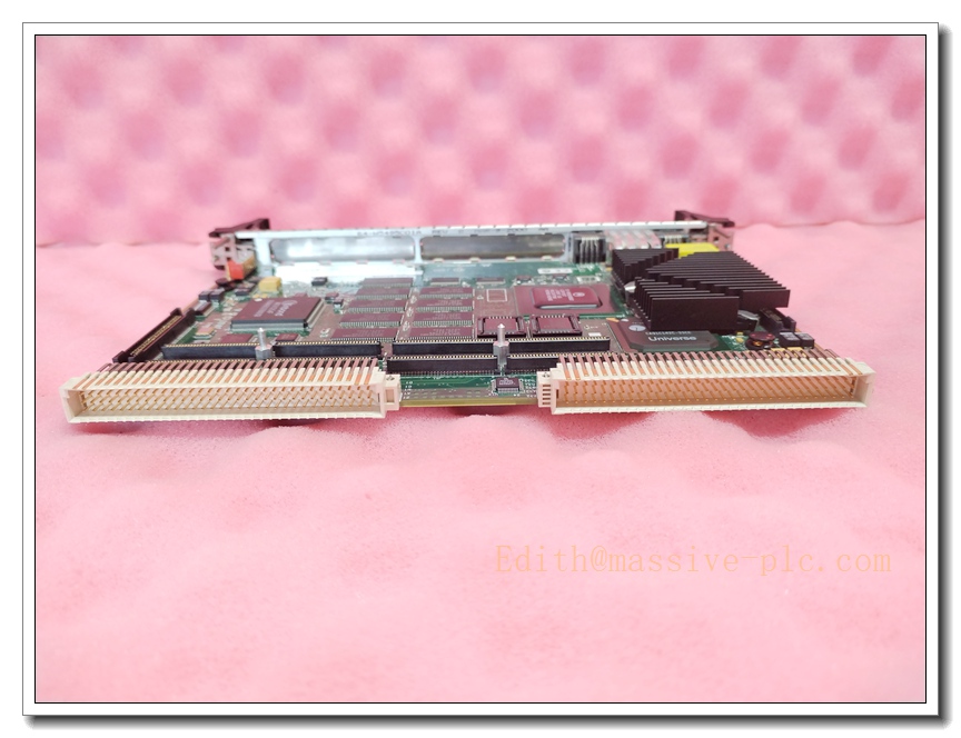
The Motorola MVME2432 is a high-performance VME64 single-board computer belonging to the MVME2400 PowerPlus II embedded series, designed as the core CPU controller for VMEbus rack systems. Powered by MPC750 PowerPC RISC processor, this board integrates ECC memory, onboard flash firmware storage, battery-backed NVRAM, 10/100 Ethernet, dual serial debug ports and dual PMC mezzanine expansion slots. It acts as the master system controller to execute real-time control logic, data acquisition, fault logging and host communication for mission-critical industrial and aerospace platforms. The Universe II PCI-VME bridge chip enables high-speed master/slave data transfer across the VME backplane, supporting reliable deterministic operation for long-life legacy control racks. This unit is widely stocked as a critical spare for turbine control, nuclear monitoring and offshore automation systems where service life spans multiple decades.
MVME2432
Technical Specifications
| Item | Parameter |
|---|---|
| Model | MVME2432 |
| Brand | Motorola (Embedded VME Division) |
| Form Factor | 6U VME single slot board |
| Processor | MPC750 PowerPC |
| Clock Speed | 350 MHz typical |
| Cache | 32 KB L1 Instruction / 32 KB L1 Data, 1 MB L2 Backside Cache |
| Memory | 64 MB ECC SDRAM (expandable) |
| Firmware Storage | 8 MB Onboard Flash |
| Non-Volatile Memory | 8 KB Battery-backed NVRAM + Real-Time Clock |
| Bus Interface | VME64 (VITA 1-1994), A24/A32 addressing, VME master/slave |
| Expansion | Dual 32/64-bit PMC slots |
| Network | Single 10/100BASE-T Ethernet (RJ45 front panel) |
| Serial Ports | 2 × RS232/RS422 debug serial ports |
| Power Input | +5 VDC, ±12 VDC from VME backplane |
| Typical Power Draw | 18 W |
| Operating Temperature | 0°C ~ +60°C commercial; -40°C ~ +70°C conformal coated version |
| Storage Temperature | -40°C ~ +85°C |
| Supported OS | VxWorks, LynxOS, QNX, Embedded Linux |
| Onboard Functions | Watchdog timer, self-test diagnostics, status LED indicators |
Compatibility & Installation Traps
Compatibility
- Works with VME64-compliant backplanes and 6U VME rack chassis; supports system controller mode for the VME bus.
- Compatible with PMC mezzanine I/O modules following IEEE P1386.1 standard.
- Requires matching VxWorks boot firmware and board support package; boot ROM revisions must align with application software.
- Not pin or firmware compatible with earlier MVME2400 variants or MVME2700 series; backplane arbitration and memory mapping differ.
Common Installation Traps
- Improper VME backplane slot assignment; only one board can be set as VME system controller per rack, conflicting arbitration causes bus lockup.
- Battery depletion of onboard NVRAM; loss of boot parameters and network settings leads to boot failure after replacement.
- Hot-swap insertion while rack power is active; backplane transients damage the VME interface ASIC and processor core.
- Mismatched PMC mezzanine cards; 64-bit PMC modules may require special jumper settings on the MVME2432.
- Inadequate cabinet cooling; high rack temperature triggers watchdog resets and memory ECC errors.
- Incorrect boot ROM configuration; wrong MAC address or boot device prevents network loading of the runtime OS.
- Ignoring ESD protection; the exposed memory and PMC connectors are sensitive to electrostatic discharge.
- Mixing VME64 and older VME32-only backplanes without verifying bus timing; intermittent bus errors and data corruption occur under heavy load.
Standard Operating Procedure (SOP)
- Pre-inspection: Inspect MVME2432 for bent edge fingers, component damage, corrosion on PMC connectors and battery leakage. Confirm part number and revision match the original CPU board.
- Lockout and isolation: Cut off VME rack main power, verify zero voltage on the backplane with a multimeter.
- ESD preparation: Wear an ESD wrist strap and use an anti-static work surface during handling.
- Board extraction: Unlatch the front panel ejectors, slide the faulty board smoothly out of the VME slot. Remove PMC daughter cards carefully and label each module.
- Mount new CPU board: Insert MVME2432 into the target slot, seat fully against the backplane and close both ejector latches. Reinstall PMC modules with proper alignment.
- Jumper and configuration check: Verify VME system controller jumpers, PMC mode settings and NVRAM battery condition.
- Power-up and boot test: Restore rack power, observe front panel diagnostic LEDs, enter boot monitor and confirm memory and Ethernet initialization.
- Software commissioning: Load the validated VxWorks BSP and application image, restore network parameters, IP addresses and I/O mapping. Run board self-test and VME bus diagnostic.
- Final validation: Execute full rack I/O testing, confirm communication with other VME slave modules, save boot parameters and return the system to operational status.
MVME2432
Application Scenarios
- Gas and steam turbine control VME rack main CPU
- Nuclear plant safety monitoring and protection systems
- Offshore oil & gas platform critical control cabinets
- Aerospace test stand and ground support equipment
- Legacy military embedded computing platforms
- Power generation generator control and protection
- Railway signal and rolling stock onboard control
- Industrial test and measurement real-time data systems
Matching Components
- 6U VME64 rack chassis and compliant backplane
- PMC serial, analog I/O or fieldbus mezzanine modules
- VME rack regulated +5 V / ±12 V power supply
- ESD workstation kit and anti-static storage tray
- VxWorks board support package and boot firmware
- Shielded Ethernet and serial console cables
- Replacement NVRAM battery pack
- VME diagnostic software and debug terminal adapter
Recommended Related Models (8)
- MVME2431
- MVME2433
- MVME2434
- MVME2435
- MVME2500
- MVME2604
- MVME2700
- MVME3100



 Start Chat




