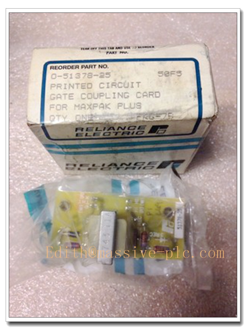
Description
Product Core Overview
The Reliance Electric 0-51378-25 (now under Rockwell Automation) is a classic industrial control module belonging to the Reliance Automax / SLC 500 series product family. It has two mainstream industrial application definitions: one is a high-power DC drive gate coupling board for thyristor trigger control, and the other is an 8-channel independent relay output module for Allen-Bradley SLC 500 PLC systems. It delivers ultra-high trigger synchronization accuracy, 2500V full electrical isolation and long MTBF over 60,000 hours. With robust industrial-grade design, it is widely deployed in metallurgical rolling mills, large DC motor speed regulation systems and general industrial automation production lines worldwide, ensuring long-term stable operation even in harsh high-temperature industrial environments .
Key Technical Specifications
- Official Part Number: 0-51378-25
- Manufacturer: Reliance Electric (acquired by Rockwell Automation)
- Product Type 1: High-power DC drive gate coupling board
- Product Type 2: 8-channel independent relay output module
- Rated Power Supply: 24V DC (system backplane power supply)
- Output Performance (Relay Version): 2A per point @ 240V AC / 2A @ 125V DC, 8 independent channels
- Isolation Performance: 2500V RMS full electrical isolation between channel-to-backplane
- Trigger Synchronization Accuracy (Gate Board Version): <1μs, no system harmonic interference
- MTBF: Over 60,000 hours
- Operating Temperature Range: -20°C to +85°C (gate board version); 0°C to +60°C (relay output version)
- Installation Method: Standard DIN rail / rack direct plug-in installation
- Communication Protocol: Native support for Reliance Automax dedicated industrial communication protocol
- Net Weight: Approximately 1.1kg
- Compliance Standards: UL, CSA, CE industrial safety certification
8 Recommended Related Series Models
- 0-51378-24: Reliance direct drop-in replacement model, fully pin-compatible with 0-51378-25
- 86466-58R: Reliance full series rectifier component, natively paired with the gate coupling board version
- 1746-OW4: Rockwell SLC 500 series relay output module, 100% pin-compatible with the relay version of 0-51378-25
- 61C350: Reliance Automax series PLC processor module, the native host platform for this module
- 57C332A: Reliance general-purpose PLC control module, for system logic expansion
- ABB AC 800M: Distributed Control System, for full plant automation system integration
- ABB PP845 3BSE042235R1: Industrial HMI operator panel, providing on-site drive system operation and fault visualization interface
- WR-D4007: Reliance redundant power supply module, delivering stable 24V DC redundant power for the control system rack
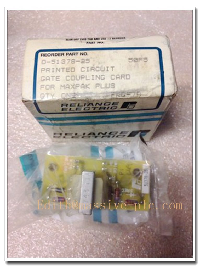
Reliance Electric 0-51378-25
Professional Quality Control Test Standard Operating Procedure
- Pre-Test Visual Audit: Inspect the module PCB for physical damage, corroded backplane pins or loose components; confirm front panel status LEDs and rack locking mechanisms are fully intact
- Power Stress Validation: Insert the unit into a certified Reliance test chassis, apply variable 24V DC input across full operating range, verify no overcurrent, overheating or unexpected shutdown occurs
- Core Performance Test: For gate board version, test thyristor trigger synchronization accuracy, confirm deviation <1μs; for relay version, test every channel contact action performance, confirm no contact adhesion or abnormal resistance
- Isolation Performance Test: Apply 2500V AC dielectric strength test between field signal side and control backplane side, confirm no breakdown occurs and isolation resistance meets safety requirements
- Communication Validation: Connect the module to certified test devices, run 72-hour continuous data transmission test, confirm zero packet loss and no communication dropout under industrial electrical noise simulation
- Environmental Temperature Cycling: Place the module in an environmental chamber, run full functional validation across full operating temperature range, confirm no performance degradation or unexpected fault trips at extreme temperature limits
- Vibration Resistance Test: Simulate industrial 5–500Hz vibration environment, confirm no loose internal components or unstable signal output occurs
- Final Documentation: Record all test metrics and performance data in the official Reliance quality log, assign unique serial number traceability tag, and issue formal performance certification report before shipment
New Module Installation Guidelines
- Pre-Installation Preparation: Power down the target control rack completely, confirm 24V DC power supply output is stable, wear certified ESD wrist strap connected to the chassis grounding point before handling the module
- Slot Configuration: Insert the new 0-51378-25 module into the designated slot in the control rack, ensure no adjacent slots are occupied by incompatible non-Reliance modules that may cause backplane signal conflicts
- Mechanical Mating: Carefully align the module with the chassis DIN guide rails, push it smoothly into the slot until the rear edge connector fully mates with the system backplane, then lock the front panel mounting screws to recommended torque of 0.8Nm
- Signal Cabling Connection: Connect all field signal cables using shielded industrial cables, strictly separate low-level signal cables from high-power VFD motor cables to eliminate electrical interference
- Power-Up and Initial Diagnostic: Restore power supply, observe front panel status LEDs; confirm the module completes boot process and enters normal running state within 60 seconds, verify the module appears online in the Reliance / Rockwell control system diagnostic software
- Full System Validation: Perform full loop test, confirm all thyristor trigger signals / relay output actions respond correctly before transferring the industrial control system to normal operation mode
Application Scenarios and Features
- Metallurgical Rolling Mill DC Drive Control: Deployed in large metallurgical rolling mill DC drive systems, the <1μs trigger synchronization accuracy ensures stable operation of high-power rectifier systems, no harmonic interference occurs
- Large Industrial DC Motor Speed Regulation: Used in mining and port large DC motor speed control systems, the 60,000+ hours MTBF drastically reduces unplanned equipment downtime
- General Industrial PLC Output Control: Applied in packaging lines, water treatment systems and HVAC automation, the 8 independent relay channels support mixed AC/DC load control, no intermediate relay required
- Legacy Reliance / SLC 500 System Modernization: Acts as the official drop-in replacement for older 0-51378-25 series modules, preserving all existing backplane wiring and control program configuration to minimize system downtime during hardware replacement
Frequently Asked Questions
- Q: My module reports “Trigger Sync Fault” alarm after installation, what is the most common root cause?
A: 90% of this fault is caused by improper trigger signal cable attenuation. First check the signal cable integrity and connector locking status, confirm no signal attenuation exceeds the system allowable threshold. - Q: Can I replace an older 0-51378-25 unit with this new unit directly without reconfiguration?
A: Yes, the 0-51378-25 is fully pin-compatible and functionally identical to all earlier revisions, you can perform a direct drop-in replacement without any system configuration modification. - Q: What is the maximum electrical isolation performance this module can provide?
A: The 0-51378-25 delivers 2500V RMS full electrical isolation between field side and control backplane side, effectively blocking surge voltage and ground potential difference impact. - Q: Does this module support mixed AC/DC load control?
A: Yes, the relay version of 0-51378-25 supports 2A @ 240V AC and 2A @ 125V DC mixed load control, no polarity limitation for relay contacts.