
Description
SYN5201A-Z.V5271 (3BHB006714R0271) Product Technical Manual
Product Core Introduction
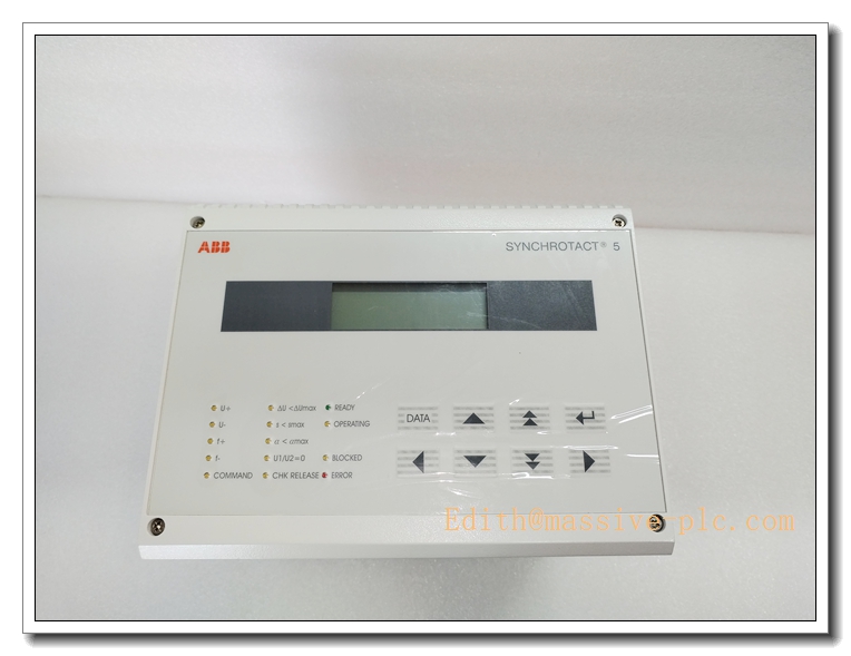
The SYN5201A-Z.V5271, order code 3BHB006714R0271, is an ABB SYNCHROTACT 5 automatic single-channel synchronizing unit, dedicated for generator and busbar paralleling in power plant control systems. It precisely measures voltage magnitude, phase angle and frequency difference between generator side and grid side, calculates the optimal closing advance time, and sends breaker closing command to achieve bumpless synchronization. This unit integrates synchronizing logic, signal conditioning, fault monitoring and relay output. Widely deployed in thermal, hydro and gas turbine generator control cabinets, it is a critical spare for legacy ABB power control systems. It complies with IEC 61508 SIL2 functional safety requirements for power synchronization protection.
SYN5201A-Z.V5271 3BHB006714R0271
Main Technical Specifications
- Model: SYN5201A-Z.V5271, Order No.: 3BHB006714R0271
- Power Supply: 24VDC, operating range 9–36VDC
- Power Consumption: Max 14W
- Synchronizing Channels: Single-channel automatic synchronizing
- Measured Signals: Generator voltage, grid voltage (AC voltage input)
- Measurement Accuracy: Voltage ±0.2%, frequency ±0.01Hz, phase angle ±0.1°
- Relay Output: Breaker closing output, alarm relay output; contact rating 250VAC / 5A
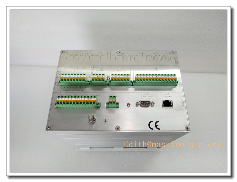
- Communication Interfaces: RS485, PROFIBUS DP
- Supported Protocol: Modbus RTU, PROFIBUS DP
- Operating Temperature: -20°C ~ +60°C
- Storage Temperature: -40°C ~ +85°C
- Relative Humidity: 5%–95% RH, non-condensing
- Dielectric Withstand Voltage: 1500V AC galvanic isolation between AC measuring circuit and control logic
- Protection Class: IP20 (cabinet flush panel mounting)
- MTBF: ≥100,000 hours
- Mounting: Cabinet door flush mounting
- Dimension: 221mm × 163mm × 220mm
- Net Weight: 4.0 kg
- Status Indicators: Power, Run, Sync Ready, Close Command, Fault LED indicators
Recommended Homologous Series Models
- SYN5201A-Z.V5277 (3BHB006714R0277): Updated firmware revision, improved anti-interference for high EMI power plant environments, form-fit-function compatible replacement.
- SYN5202: Dual-channel synchronizing unit, supporting two independent generator/busbar paralleling loops.
- SYN5101: Compact basic synchronizing module for small generator units with simplified function.
- SYN5302: Large multi-channel synchronizer for multi-generator station central paralleling control.
Professional Quality Control & Test Standard Operating Procedures (SOP)
4.1 General Test Standard
All SYN5201A-Z.V5271 units are inspected complying with ISO9001, IEC61131, IEC61000 EMC and IEC61508 SIL2 standards. Each unit carries unique serial number for full lifecycle traceability.
4.2 Core Test SOP
- Visual & Mechanical Inspection: Inspect front panel, housing, sealing gasket, AC voltage terminals and communication connectors for scratches, cracks and damage; verify panel cutout dimension and mounting bracket fit against engineering drawings.
- Power-On Basic Function Test: Apply minimum, rated and maximum 24VDC supply; validate power and run LED; confirm no overcurrent or short-circuit condition.
- Synchronizing Measurement Calibration Test: Inject adjustable AC voltage, frequency and phase difference signal to generator and grid input terminals; verify measurement precision of voltage, frequency and angle; check automatic advance time calculation.
- Close Logic & Relay Output Test: Simulate qualified synchronizing condition; verify the unit outputs closing relay pulse at calculated advance moment; test alarm relay trigger for abnormal synchronizing conditions.
- Communication Interface Test: Connect the unit to test controller via RS485 / PROFIBUS; read measured electrical parameters, synchronizing status and fault information, verify stable cyclic data exchange.
- EMC Immunity Test: Conduct ESD, electrical fast transient burst, surge and radiated interference test per IEC61000; confirm no false closing command, measurement distortion or false fault alarm.
- Temperature Cycling Test: -20°C ↔ +60°C thermal cycling for 40 cycles, 2 hours per cycle; validate measurement accuracy and synchronizing logic stability under temperature variation.
- Vibration & Shock Test: 10–150Hz sinusoidal vibration and mechanical shock test to validate PCB, relay solder joints and terminal retention for power plant cabinet vibration environment.
- Continuous Burn-In Aging: 160 hours burn-in at 50°C with simulated AC synchronizing signals running continuously; monitor measurement stability and relay action reliability to screen intermittent hidden faults.
- Final Calibration & Packaging: Reset factory parameters, re-calibrate measurement channels, record serial number, pack with anti-static bag and attach inspection certificate.
SYN5201A-Z.V5271 3BHB006714R0271
New Module Installation Guidelines
5.1 Pre-installation Preparation
Cut off cabinet control power and PT secondary power supply; confirm model and part number match purchase order; inspect panel, gasket and terminals for integrity. Wear anti-static wristband before handling internal circuit board. Prepare screwdriver, torque screwdriver, shielded communication cable and Synquick commissioning software on laptop.
5.2 Installation Steps
- Machine the cabinet door cutout following dimension drawing; clean aperture edge and remove burrs.
- Fit rubber sealing gasket on front frame; insert SYN5201A-Z.V5271 from cabinet front into the cutout.
- Fasten rear mounting brackets evenly with specified torque to compress gasket and maintain cabinet protection.
- Wire PT secondary AC voltage signals to voltage input terminals; strictly follow PT secondary grounding and short-circuit safety specification.
- Wire relay output to breaker closing circuit; connect shielded RS485 / PROFIBUS communication cable to DCS or controller.
- Wire 24VDC control power; tighten terminal screws, confirm no bare copper exposure and correct polarity. Separate AC measurement cables from high-power cables.
5.3 Post-installation Commissioning
Restore cabinet 24VDC control power, keep PT secondary in test state; energize synchronizing unit and observe LED indicators to confirm normal power and boot status. Connect laptop and run Synquick tool to configure generator parameters, synchronizing threshold and breaker closing time. Perform static signal injection test to verify voltage/frequency/angle reading. Conduct full simulation synchronizing test, check closing command timing and alarm function. Run continuous 60-minute stability test before applying to live generator PT circuit and online operation.
Application Scenarios & Product Features
6.1 Core Application Scenarios
- Thermal power plant generator auto-synchronizing and breaker paralleling control
- Hydroelectric turbine generator grid connection synchronizing cabinet
- Gas turbine combined cycle unit synchronizing and grid paralleling
- Power station busbar tie switch automatic paralleling
- Legacy ABB SYNCHROTACT5 system spare replacement and cabinet retrofit
6.2 Core Product Features
- ABB SYNCHROTACT5 single-channel automatic generator synchronizing unit
- High-precision measurement for voltage, frequency and phase difference between generator and grid
- Automatic prediction of breaker closing advance time to achieve bumpless paralleling
- Built-in abnormal condition protection: out-of-limit voltage, frequency, angle block closing command
- Relay output for breaker close and fault alarm; SIL2 safety certification
- Multi-protocol serial communication for uploading synchronizing status and measured values to DCS
- Flush panel mounting design, front panel status LED for local operation observation
- High EMC immunity, stable performance under strong electromagnetic interference in power plant switchgear room
SYN5201A-Z.V5271 3BHB006714R0271
Frequently Asked Questions (FAQ)
Q1: Power LED off after installation A1: Verify 24VDC supply voltage and polarity; inspect loose terminals or broken wiring; measure terminal voltage. If input voltage normal while LED stays off, replace the synchronizing unit.
Q2: Voltage measurement reading is abnormal or drifting A2: Check PT secondary wiring and grounding; inspect PT circuit open/short risk; verify wiring polarity of voltage input terminals; check signal cable shielding and ground loop.
Q3: Synchronizing ready LED never lights up A3: Check generator and grid voltage magnitude, frequency and phase difference; review configured synchronizing threshold parameters in Synquick; confirm PT signal wiring is correct.
Q4: No closing command output even when synchronizing condition satisfied A4: Check breaker ready contact input; verify closing relay wiring and loop continuity; check interlock blocking signal from external protection system.
Q5: Unit reports fault alarm randomly A5: Check cabinet temperature and vibration; inspect AC input surge interference; run built-in self-test via Synquick; check terminal oxidation or loose wiring.
A6: No. This is single-channel synchronizing unit. For two independent generators, two SYN5201 units or SYN5202 dual-channel model shall be adopted.


 Start Chat




