
Description
SUE3000 1VCR007346 Product Technical Manual
Product Core Introduction
The SUE3000, part number 1VCR007346, is the operator HMI panel for ABB SUE3000 High-Speed Bus Transfer System (HSTS). It serves as the local human-machine interface for motor bus transfer cabinets, used to display bus voltage, frequency, feeder status, transfer event records, fault alarms and sequence logs. Operators can execute manual bus transfer, set protection thresholds, view oscillography data and acknowledge alarms locally via this panel. Widely deployed in thermal power plants, petrochemical and large industrial critical motor load switchgear rooms, it is a standard spare replacement for legacy ABB HSTS bus transfer systems. This panel is designed for cabinet door flush mounting and communicates with the SUE3000 main control unit via serial bus.
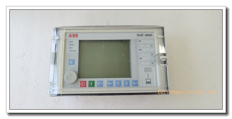
SUE3000 1VCRO07346
Main Technical Specifications
- Model: SUE3000 HMI, Order Code: 1VCR007346
- Power Supply: 110~240VDC, operating range 88–264VDC
- Power Consumption: Max 18W
- Display: 5.7-inch STN LCD, membrane keypad with rotary selector
- Local Operation Keys: Function, Start/Stop, Reset, Navigation keys
- Communication Interface: RS485, ABB proprietary bus
- Supported Protocol: SPA bus, Modbus RTU
- Operating Temperature: -20°C ~ +60°C
- Storage Temperature: -40°C ~ +85°C
- Relative Humidity: 5%–95% RH, non-condensing
- Front Panel Protection: IP54; Rear housing: IP20
- MTBF: ≥92,000 hours
- Mounting: Cabinet door flush panel mounting
- Dimension: 240 mm × 160 mm × 55 mm
- Net Weight: 0.95 kg
- Status Indicators: Ready, Transfer Active, Fault, Alarm LED indicators
Recommended Homologous Series Models
- 1VCR007346G0028: Standard revision of SUE3000 HMI panel, most commonly used spare part.
- 1VCR007346G0032: Updated firmware variant, enhanced event recording and anti-interference for high EMI power plant environments.
- 2RCA029395A0027: New generation replacement HMI for SUE3000 retrofit projects, form-fit compatible.
- SUE3000 Main Control Unit: Matching core controller for high-speed bus transfer logic.
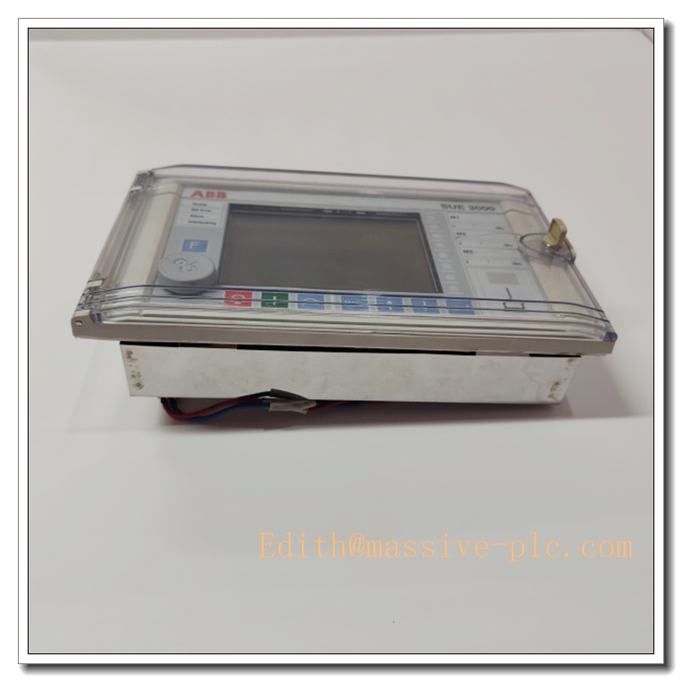
SUE3000 1VCRO07346
Professional Quality Control & Test Standard Operating Procedures (SOP)
4.1 General Test Standard
All HMI panels are inspected complying with ISO9001, IEC61131 and IEC61000 EMC standards. Each unit carries unique serial number for full lifecycle traceability.
4.2 Core Test SOP
- Visual & Mechanical Inspection: Inspect front membrane keypad, LCD screen, sealing gasket, terminal blocks and communication connectors for scratches, cracks and damage; verify panel cutout dimension and mounting bracket fit against engineering drawings.
- Power-On Basic Function Test: Apply minimum, rated and maximum DC supply; validate power, ready and fault LED; check LCD display and keypad response, confirm no overcurrent or short-circuit.
- Keypad & Display Function Test: Test all membrane keys and rotary knob; verify screen display uniformity, check for dead segments; confirm menu navigation and parameter modification function.
- Communication Interface Test: Connect to main control unit via RS485 SPA bus; read bus electrical parameters, transfer status and fault event logs; verify bidirectional parameter write operation.
- EMC Immunity Test: Conduct ESD, electrical fast transient burst, surge and radiated interference test per IEC61000; confirm no screen garbling, keypad mis-trigger or communication dropout.
- Temperature Cycling Test: -20°C ↔ +60°C thermal cycling for 40 cycles, 2 hours per cycle; validate display stability and keypad reliability under temperature variation.
- Vibration & Shock Test: 10–150Hz sinusoidal vibration and mechanical shock test to validate membrane keypad, PCB solder joints and connector retention for switchgear cabinet vibration environment.
- Continuous Burn-In Aging: 160 hours burn-in at 50°C with continuous real-time data refresh; monitor display stability and communication quality to screen intermittent hidden faults.
- Final Inspection & Packaging: Reset factory parameters, record serial number, pack with anti-static bag and attach inspection certificate.
New Module Installation Guidelines
5.1 Pre-installation Preparation
Cut off cabinet control power and main unit power; confirm model and part number match purchase order; inspect panel, gasket and terminals for integrity. Wear anti-static wristband before handling internal circuit board. Prepare screwdriver, torque screwdriver and shielded SPA communication cable for commissioning.
5.2 Installation Steps
- Machine cabinet door cutout following dimension drawing; clean aperture edge and remove burrs.
- Fit rubber sealing gasket on front frame; insert HMI panel from cabinet front into the cutout.
- Fasten rear mounting brackets evenly with specified torque to compress gasket and maintain IP54 front protection.
- Wire 110~240VDC control power to power terminals; connect shielded RS485 SPA bus cable to main control unit.
- Tighten terminal screws; confirm correct power polarity and no bare copper exposure. Separate communication cables from high-power and PT secondary cables.
5.3 Post-installation Commissioning
Restore cabinet control power and energize HMI panel; observe LED indicators to confirm normal power and boot status. Configure panel station address and communication baud rate matching main controller. Verify real-time bus voltage, feeder status and alarm message display. Test manual transfer command and parameter modification function. Run continuous 60-minute stability test; confirm event recording and alarm acknowledgement function before formal online operation.
Application Scenarios & Product Features
6.1 Core Application Scenarios
- Thermal power plant critical motor cabinet high-speed bus transfer system local operation panel
- Petrochemical plant medium voltage switchgear HSTS bus transfer monitoring and operation
- Large industrial compressor / pump motor power supply fast transfer cabinet
- Power station auxiliary power automatic switching system local human-machine interface
- Legacy ABB HSTS system spare replacement and cabinet retrofit
6.2 Core Product Features
- Dedicated local HMI panel for ABB high-speed motor bus transfer system
- 5.7-inch LCD + membrane keypad, supports local manual transfer and parameter configuration
- Real-time display of bus voltage, frequency, feeder status, fault alarms and transfer event sequence of records
- IP54 front panel protection, suitable for dusty switchgear cabinet door installation
- SPA / Modbus RTU serial communication to exchange data with main controller
- Built-in fault event storage, can record historical transfer actions and disturbance waveforms
- High EMC immunity, stable performance under strong electromagnetic interference in medium voltage switchgear room
Frequently Asked Questions (FAQ)
Q1: Power LED off after installation A1: Verify 110~240VDC supply voltage and polarity; inspect loose terminals or broken wiring; measure terminal voltage. If input voltage normal while LED stays off, replace the HMI panel.
Q2: LCD screen blank or segment missing A2: Check power supply ripple and cabinet temperature; re-seat internal display connector; inspect LCD aging or physical damage. Replace display assembly if hardware damage occurs.
A3: Check shielded SPA bus wiring and grounding; verify baud rate and station address matching; eliminate ground loop interference; check bus termination resistor.
Q4: Keypad no response or random false trigger A4: Check membrane keypad for moisture, dust or physical damage; re-seat keypad ribbon cable; inspect front gasket sealing condition to prevent moisture ingress.
Q5: Transfer event records fail to save A5: Check panel internal non-volatile memory status; run built-in self-test; confirm communication with main unit is stable during transfer event.
A6: No. This panel is only the operator interface. All bus transfer logic and signal measurement are executed by main control unit. It cannot operate standalone.



 Start Chat




