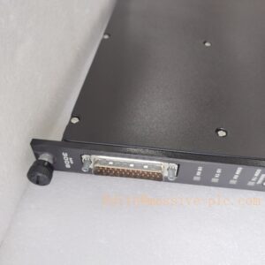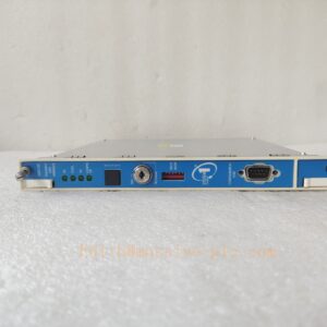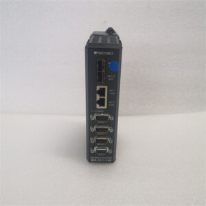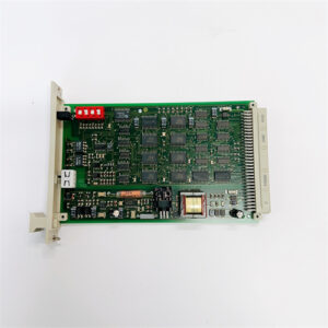
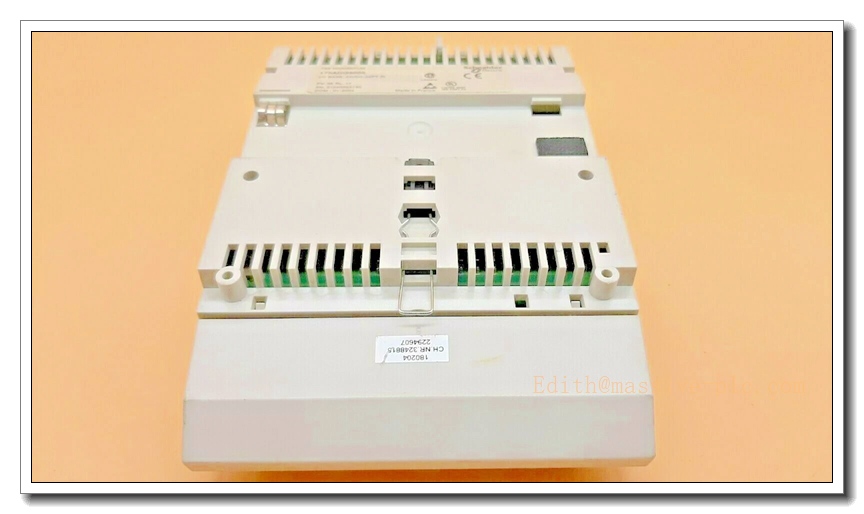
Description
SCHNEIDER 170INT11003 — Modicon Momentum INTERBUS Communication Adaptor, Twisted Pair, SUPI 3
Brand & Model Title
Schneider Electric (Modicon / Telemecanique heritage) 170INT11003 — Modicon Momentum Automation Platform, INTERBUS Communication Adaptor, Twisted Pair Medium, SUPI 3 Protocol Chip (TSX Momentum Bus Adapter for INTERBUS, Copper)
The 170INT11003 is the copper (twisted-pair) INTERBUS bus adapter of the Modicon Momentum family — the snap-on adaptor that converts any TSX Momentum I/O unit into a node on an INTERBUS remote bus, per INTERBUS standard DIN 19258. Momentum hardware is built from four snap-together elements (adaptor, I/O base, processor/option adapter, cover), and this part snaps directly onto the I/O base, taking its 5 V DC supply from that base. It operates with the SUPI 3 INTERBUS protocol chip and carries the full diagnostic functionality of INTERBUS firmware Generation 4, supporting modules with up to 16 words of I/O. Its sibling for fibre-optic rings is the 170 INT 120 00; fibre adapters OPTOSUB / OPTOSUB-PLUS can be fitted to the copper version.
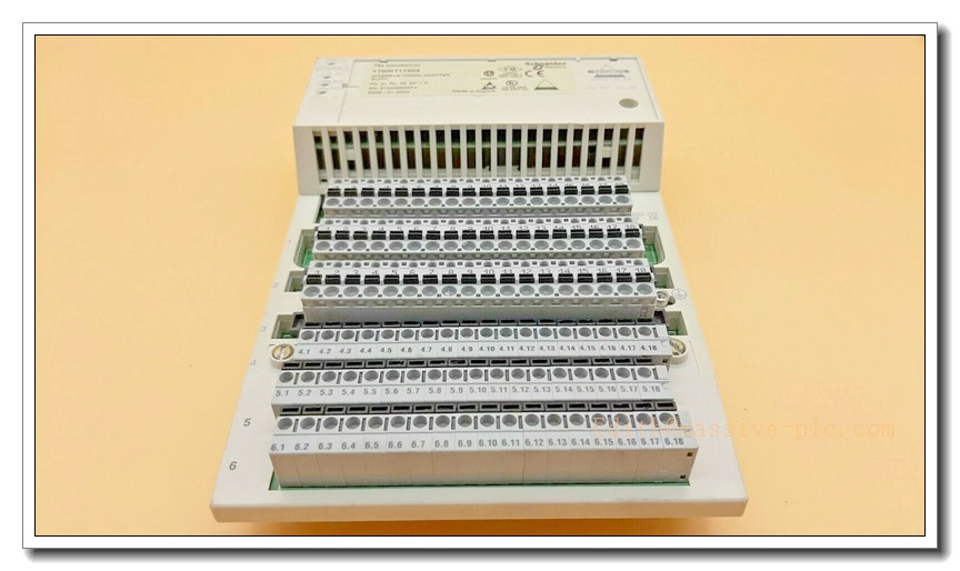
170INT11003
Main Technical Specifications
| Parameter | Value |
|---|---|
| Product type | INTERBUS communication adaptor (bus adapter snapped onto Momentum I/O base) |
| Protocol | INTERBUS Generation SUPI 3 — Generation 4 firmware diagnostics, DIN 19258 |
| Access method | Master/slave, continuous shift register (deterministic cycle timing) |
| Transmission rate | 500 kbit/s (fixed INTERBUS rate) |
| Medium / connectors | Shielded twisted pair; 2 × SUB-D 9 (incoming bus: pins; outgoing bus: sockets), RS-485 interfaces |
| Topology | Ring (remote bus and remote bus branch) |
| Devices per segment | 0…254 |
| Distances | ≤ 12,800 m total bus length; ≤ 400 m between two modules |
| Data integrity | CRC-16 control parameter; defined fail-safe state on bus interruption |
| Supply | From the I/O base, 5 V DC; current consumption < 200 mA (no fibre adapter), < 400 mA (with 2 fibre adapters) |
| Power loss | 0.8 W typical (without fibre-optic adapter) |
| Isolation | Incoming remote bus potentially isolated from logic; outgoing bus not isolated |
| Signalling | 4 LEDs — UL (logic supply), RC (remote bus check), BA (bus active), RD (remote bus disabled) |
| Weight | 0.07 kg |
| Protection | IP20; TC protective treatment; cabinet installation |
| EMC | ESD 4 kV contact / 8 kV air (IEC 801-2); EM fields 10 V/m, 80–1000 MHz (IEC 801-3) |
| Environment | Operating 0…60 °C; storage −40…85 °C; 95 % RH non-condensing; altitude ≤ 5000 m |
| Certifications | CE, UL, CSA, FM Class 1 Division 2 |
| Fibre option | OPTOSUB / OPTOSUB-PLUS adapters; all-fibre sibling 170 INT 120 00 |
| Status | Schneider lists the part as normally stocked; Momentum is a legacy platform in run-out — order early |
Typical Applications
- INTERBUS remote bus nodes — joining Momentum I/O bases (digital, analogue, counter units) to an INTERBUS ring run from a master PLC, the classic European distributed-I/O architecture of the 1990s/2000s
- Material handling and simple machine control — conveyors, packaging and intralogistics lines where the deterministic shift-register cycle and 12.8 km reach cover long machine lines without switches or repeaters
- Infrastructure and energy — distributed monitoring points along water treatment, energy and building infrastructure
- Ring extension and branch drops — the adapter is usable on both the remote bus and remote bus branches, so new I/O groups can be grafted onto an existing ring by registering the node at the master
- Legacy life extension — replacing failed Momentum drops in plants where the INTERBUS trunk, master and cabling are healthy but the I/O family has gone into run-out
Related News & Events
- Verification quality is unusually high for this reference. The Schneider USA product page, the official characteristics datasheet (BPX-published Schneider PDF) and the Schneider user manual TSX Momentum Bus Adapter for INTERBUS all agree on every figure above — protocol chip, 500 kbit/s, 12.8 km / 400 m, 254 devices, 0.8 W, 0.07 kg, SUB-D 9 pair. The user manual additionally documents the LED meanings, the 16-word I/O limit, the potential isolation of the incoming bus only, and the fibre-adapter current budget.
- The fabrications, however, are plentiful. The same number is sold as a “PLC Analog I/O Interbus Adaptor Module” with invented 24 V DC supply, ±10 V / 0–20 mA 12-bit analogue outputs, ≤ 6 W dissipation and 0.24 kg weight (these specs belong to some unrelated analogue module); as a Modicon Premium rack-mounted communication module with “SUPI3 in a rack slot” installation instructions; and in Chinese as an M580 ePAC digital input module with invented dimensions and backplane references. One page invents a 4 W power draw, 0.04 kg weight and a three-LED display (RUN/ERR/COM) that does not exist on this adaptor. The real part is a 5 V, 0.8 W, 0.07 kg snap-on adaptor with four LEDs — nothing mounts in a rack and it has no analogue I/O whatsoever.
- Installation is mechanical, not electrical. The adaptor snaps onto the Momentum I/O base and powers from it; the field-side work is entirely in the INTERBUS twisted-pair ring — shielded cable, correct DE-9 pinout, and the ring continuity that the RC/BA LEDs verify. There is no separate power wiring and no configuration on the adaptor itself; node identity lives in the master’s INTERBUS configuration.
- The RD LED is the one to watch. “Remote Bus Disabled” indicates the extended remote bus segment is switched off — a common misdiagnosis as a hardware fault when it is in fact a master-side segment enable state. UL off means a base-supply problem, not a bus problem; the four LEDs let you separate supply faults, wiring faults and traffic in one glance.
- Fibre transition is built in. Where a copper run crosses a long distance, an EMI-heavy area or between buildings, OPTOSUB / OPTOSUB-PLUS fibre adapters fit this same adaptor, and the dedicated fibre variant is the 170 INT 120 00 — useful for retrofitting copper Momentum rings onto fibre trunks without replacing I/O.
- Lifecycle: Momentum is a legacy Schneider offer still carried in some distribution stock, but it is platform run-out; one reseller already marks the part discontinued while the official page still shows normally stocked. INTERBUS itself survives through Phoenix Contact and host migrations; the Momentum-side forward path is Schneider’s documented M258/M340 or Modicon M221-era transition offers. Buy from channels offering verifiable date codes — and disregard every listing that quotes analogue ranges, rack slots or 24 V supplies for this reference.