
Description
Rolls-Royce H1127-0101 Marine Propulsion & Thruster Controller, Unified Platform Series
Product Description
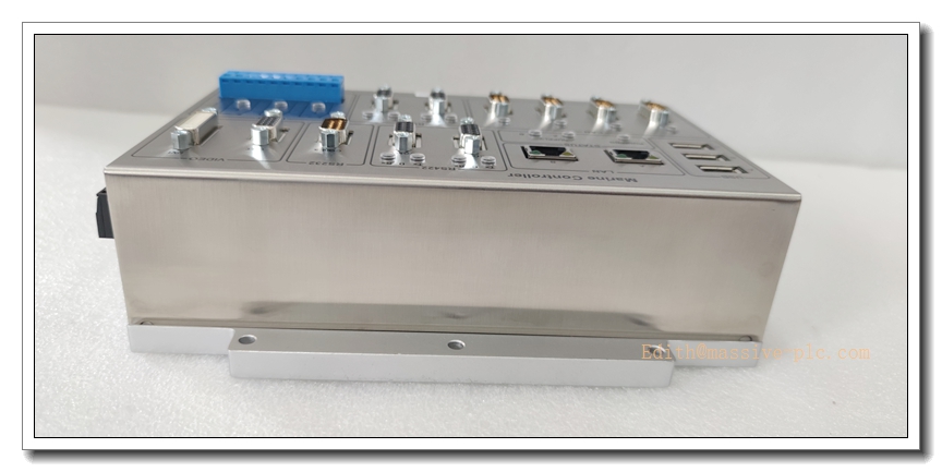
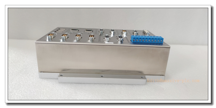
The H1127-0101 (alternate marking H1127.0101, spare code 000068308 / 5000068308) is a marine-grade dedicated controller developed by Rolls-Royce Marine, now part of the Kongsberg Maritime ecosystem. It serves as a core control unit within the Unified Platform marine automation architecture, delivering closed-loop regulation for azimuth thrusters, tunnel thrusters and propulsion machinery. This controller integrates on-board digital and analog I/O, multi-channel CAN bus, RS422 serial and Ethernet interfaces for vessel network communication. With marine conformal coating to resist salt mist, humidity and vibration, it supports dynamic positioning (DP), local thruster control, alarm monitoring and safe shutdown logic. It is programmed via Rolls-Royce proprietary marine engineering software and is commonly supplied as OEM spare for vessel retrofit and maintenance; it carries major marine classification society certifications for onboard critical machinery control.
Technical Specifications
- Brand: Rolls-Royce Marine / Kongsberg Maritime
- Part Number: H1127-0101 (H1127.0101, 000068308)
- Type: Marine Thruster & Propulsion Controller
- Supply Voltage: 24 VDC (18–30 VDC operating range)
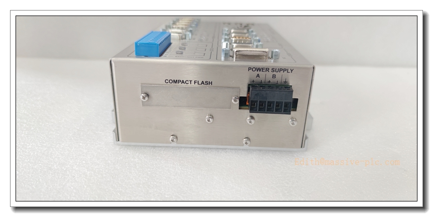
- Communication Interfaces: CAN bus, RS422, 10/100 Ethernet, CompactFlash local data storage
- I/O: Mixed isolated digital and analog channels for thruster feedback, speed command, valve actuation and ESD trip signals
- Environmental Coating: Conformal coating for salt fog and humidity resistance
- Operating Temperature: -15 °C ~ +55 °C
- Storage Temperature: -40 °C ~ +85 °C
- Relative Humidity: 5% ~ 95%, non-condensing
- Enclosure Rating: IP54 (for console mounting in wheelhouse or engine control room)
- Weight: Approx. 2.1 kg
- Compliance: DNV-GL, ABS, Lloyd’s Register marine certification
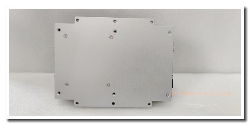
- Mounting: Cabinet/console panel mount
- Status Indication: RUN, FAULT, COMM, POWER LED indicators
H1127-0101
Application Scenarios
- Offshore vessel dynamic positioning (DP) thruster control
- Azimuth propeller and tunnel thruster maneuvering control for platform supply vessels
- Ship engine room propulsion machinery monitoring and safety trip logic
- Marine diesel genset remote control and load sharing signal interface
- Vessel bridge control station signal conversion and command distribution
- Yacht and workboat steering gear closed-loop actuator control
- Retrofit replacement for legacy Rolls-Royce Unified Platform marine control racks
- Critical marine machinery alarm and condition monitoring systems
8 Related Rolls-Royce / Kongsberg Model Recommendations
- H1127-0202 – Upgraded Unified Platform Marine Controller
- H1117-0101 – Marine Digital I/O Interface Module
- H1137-0101 – Analog Signal Conditioning Module for Thruster Feedback
- CANMAN SLIO01 – Distributed CAN I/O Slave Module
- H1147-0101 – Propulsion Safety ESD Interface Unit
- H1157-0101 – Bridge MPU Manoeuvre Processing Unit
- 0000683102 – CompactFlash Memory Card for Series
- H1167-0101 – Redundant Power Supply for Unified Platform Racks
Compatibility & Installation Pitfalls
Compatibility
- Designed exclusively for Rolls-Royce Unified Platform marine automation system; it cannot be programmed or used as a standalone general-purpose PLC.
- Requires matching proprietary engineering software; standard industrial PLC tools cannot download or edit application logic.
- Firmware revision must match the vessel’s existing thruster control software; mismatched firmware will break closed-loop positioning functions.
- CAN bus node address must follow the original vessel network topology; duplicate CAN addresses lead to total thruster communication loss.
- All I/O signal types (24VDC discrete, 4-20mA analog feedback) must align with the original vessel wiring schedule.
- This unit is marine-certified; using non-marine substitute modules invalidates vessel class certification.
Installation Pitfalls
- Isolate vessel 24VDC marine power and thruster hydraulic/pneumatic interlocks before removal; live hot-swap is not supported and may trigger unintended thruster movement.
- Use marine-grade shielded twisted-pair cables for CAN and RS422; unshielded wiring suffers severe interference under engine vibration and salt environment.
- Terminate CAN bus at the two physical endpoints only; extra termination resistors cause bus distortion and intermittent communication dropouts.
- Verify I/O polarity carefully for 4-20mA thruster feedback signals; reversed wiring produces invalid position feedback and hunting control behaviour.
- Avoid mounting near high-current starter panels and VFD drives; strong electromagnetic noise disturbs positioning precision.
- CompactFlash storage holds vessel-specific control parameters; always back up the CF card image before controller replacement.
- Confirm conformal coating integrity after maintenance; scratches on PCB coating accelerate corrosion in salt-laden engine room air.
- After replacement, full DP and thruster manoeuvre test is mandatory; simple power-up does not validate closed-loop positioning safety functions.
Standard Operating Procedure (SOP)
SOP for -0101 Marine Controller Inspection, Installation and Functional Test
- Pre-Installation Inspection Examine the controller housing, connectors and PCB for corrosion, pin damage or coating degradation. Confirm part number -0101 and cross-reference the spare serial number and firmware revision. Verify compatibility with the vessel Unified Platform network, thruster I/O schedule and class-approved control application. Review vessel lockout/tagout permits, isolate 24VDC control power and thruster safety interlocks.
- Console Installation Mount the -0101 controller in the designated control console. Terminate CAN bus, RS422, Ethernet, discrete trip and analog feedback wiring per vessel electrical drawings. Fit the CompactFlash card with validated vessel control firmware. Apply marine EMC shielding and single-point grounding; segregate signal cables from high-power motor and starter wiring.
- Software Configuration & Parameter Load Restore 24VDC control power. Launch Rolls-Royce marine configuration software and verify controller online identification. Load the vessel-specific thruster control application and calibration parameters from the backup CF image. Save a full offline backup of the control logic and calibration data. Resolve CAN bus, Ethernet and module fault alarms before local I/O testing.
- I/O and Communication Test Test each digital trip, enable and feedback point; inject calibrated 4–20mA analog signals for thruster angle and speed feedback. Simulate CAN cable disconnection and sensor fault conditions to validate alarm reporting and predefined safe-state trip behaviour. Record signal response and fault handling in the vessel commissioning log.
- Thruster and DP Commissioning Release mechanical and hydraulic interlocks only after point-level testing passes. Execute local thruster jog test, closed-loop position calibration and bridge manoeuvre station command verification. Run supervised dynamic positioning test at low power. Confirm control faults trigger controlled safe hold or shutdown instead of uncontrolled thruster rotation. Cross-check alarm signals to ship SCADA and bridge HMI.
- Return to Service Reset fault latches and acknowledge marine class required diagnostic logs. Remove lockout-tagout and close the vessel work permit. Continuously monitor CAN bus health, controller temperature and thruster position stability during the supervised sea trial observation window. Notify vessel chief engineer and DP operator the controller is ready for operational use.
- Periodic Maintenance and Replacement During vessel dry-dock or scheduled machinery overhaul, inspect connector tightness, conformal coating condition, cabinet ventilation and LED status. Execute the vessel’s DP and thruster proof-test routine. If persistent unrecoverable communication or hardware faults occur, isolate control power and thruster safety circuits before replacement. After fitting the spare controller, reload the vessel application, re-calibrate thruster feedback sensors and complete full manoeuvre and DP acceptance test before returning the vessel to service.


 Start Chat




