Description
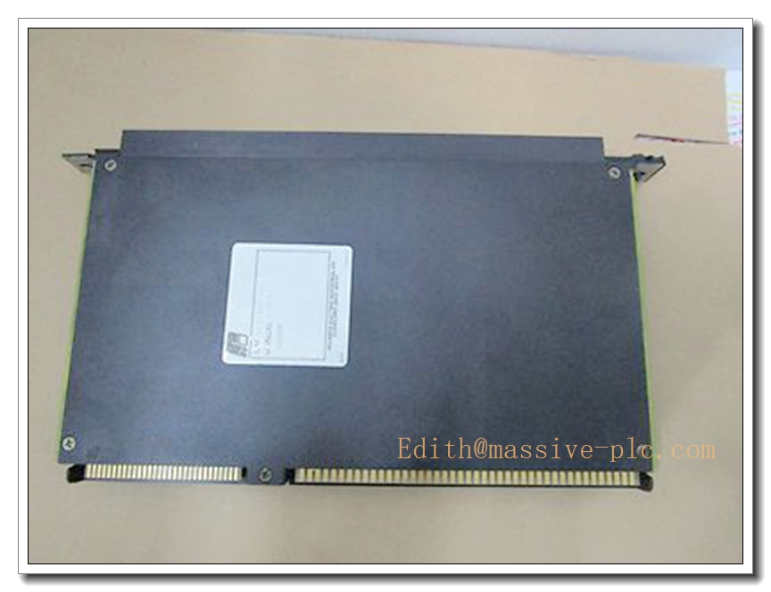
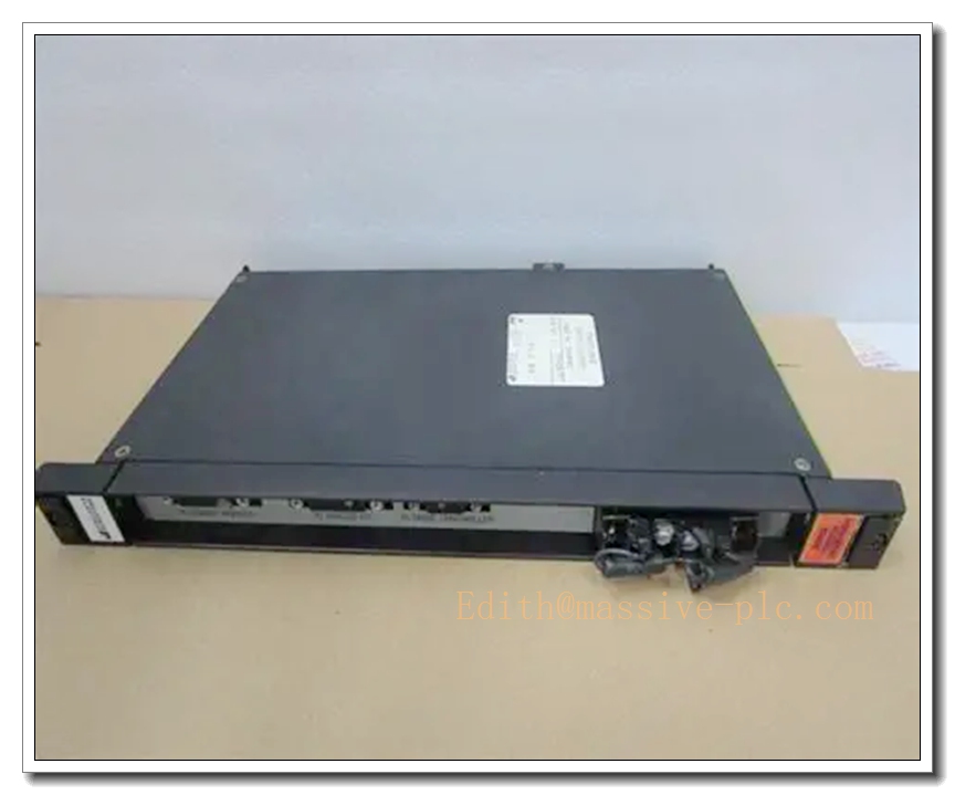
RELIANCE 0-57C407-4H Resolver Input Position Control Module, Industrial Automation Motion Feedback Card
Product Introduction
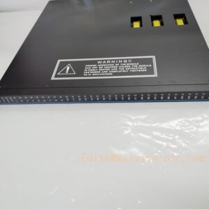
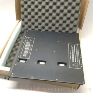
The RELIANCE 0-57C407-4H is a high-performance resolver input module engineered for precision motion and position control within heavy-duty industrial automation systems. Designed to acquire resolver signals, it converts analog resolver feedback into digital position and velocity data for host motion controllers, delivering closed-loop positioning for machine tools, metal processing lines, robotic axes, and high-speed production machinery. This rack-mountable card integrates signal conditioning, excitation drive, and high-resolution sampling circuitry, supporting stable operation under industrial electrical noise, vibration, and wide temperature environments. It complies with UL and CE industrial standards and is widely deployed in legacy Reliance motion control platforms for retrofit, spare part replacement, and system upgrade projects.
0-57C407-4H
Technical Introduction
- Product Type: Resolver Input / Position Feedback Module
- Brand: RELIANCE Electric
- Model: 0-57C407-4H
- Signal Interface: Resolver analog input, built-in resolver excitation driver
- Sampling Performance: High-resolution angular position conversion, real-time velocity calculation
- System Bus: Compatible with Reliance motion control rack backplane
- Operating Environment: Industrial grade, anti-electromagnetic interference design
- Mounting: Standard chassis rack insertion, hot-swap compatible for qualified cabinet design
- Function: Captures rotor angular position, transmits digital position/velocity values to main controller, supports multi-axis synchronous motion control, fault diagnostic of resolver wiring and signal integrity
- Application: CNC machine axes, material handling drives, rolling mill control, automated conveyor positioning systems
Adaptive Quality Assurance & Test Protocol
All 0-57C407-4H modules undergo a standardized adaptive validation sequence prior to shipment to guarantee functional integrity and long-term field reliability.
- Visual & Physical Inspection: PCB trace, solder joint, connector pin and component visual screening; check for corrosion, physical damage or oxidation.
- Power Cycle Burn-in Test: Continuous powered burn-in under nominal supply voltage, cyclic power on/off to detect early failure components.
- Resolver Signal Simulation Test: Connect precision resolver simulator to verify excitation output, position readout accuracy, noise rejection and response latency.
- Backplane Communication Test: Insert into matching system rack to validate bus handshake, data transmission and fault alarm reporting.
- EMI Immunity Adaptive Test: Apply simulated industrial noise to verify signal stability under conducted and radiated interference.
- Environmental Screening: Temperature cycling test to confirm performance consistency across operating temperature range.
- Final Functional Report: Generate unique test log for each unit; pass criteria include full signal accuracy, no communication dropout and correct fault flag triggering. All tested units come with test records for traceability.
Field Engineer Technical Notes
This resolver input module is used for closed-loop motion feedback and requires qualified field technicians for installation, commissioning and troubleshooting.
- Installation: Power down the control rack before card insertion; align backplane connector properly, secure module locking screws. Verify rack grounding is fully implemented to reduce resolver signal interference.
- Wiring: Resolver shielded cable must be routed separately from high-power drive cables; shield termination should follow single-point grounding specification to avoid ground loop noise.
- Commissioning: After power-up, run resolver offset calibration; check position reading drift, excitation amplitude and wiring fault bits. Confirm axis position tracking matches mechanical actual position.
- Troubleshooting: Common alarms include resolver open circuit, short circuit, signal loss and excitation failure. Use controller diagnostic registers to isolate wiring defects vs module hardware failure.
- Maintenance: Periodically inspect connector pins for dust and oxidation. Replace module only after full power isolation. Do not operate the axis with degraded resolver feedback to prevent mechanical collision.
- Compatibility Notice: Confirm host rack firmware and backplane version match before retrofit. Incompatible firmware may cause intermittent communication errors.
8 Related Models in the Same Series
- 0-57C407-1H
- 0-57C407-2H
- 0-57C407-3H
- 0-57C407-5H
- 0-57C407-6H
- 0-57C407-7H
- 0-57C407-8H
- 0-57C407-9H