
Description
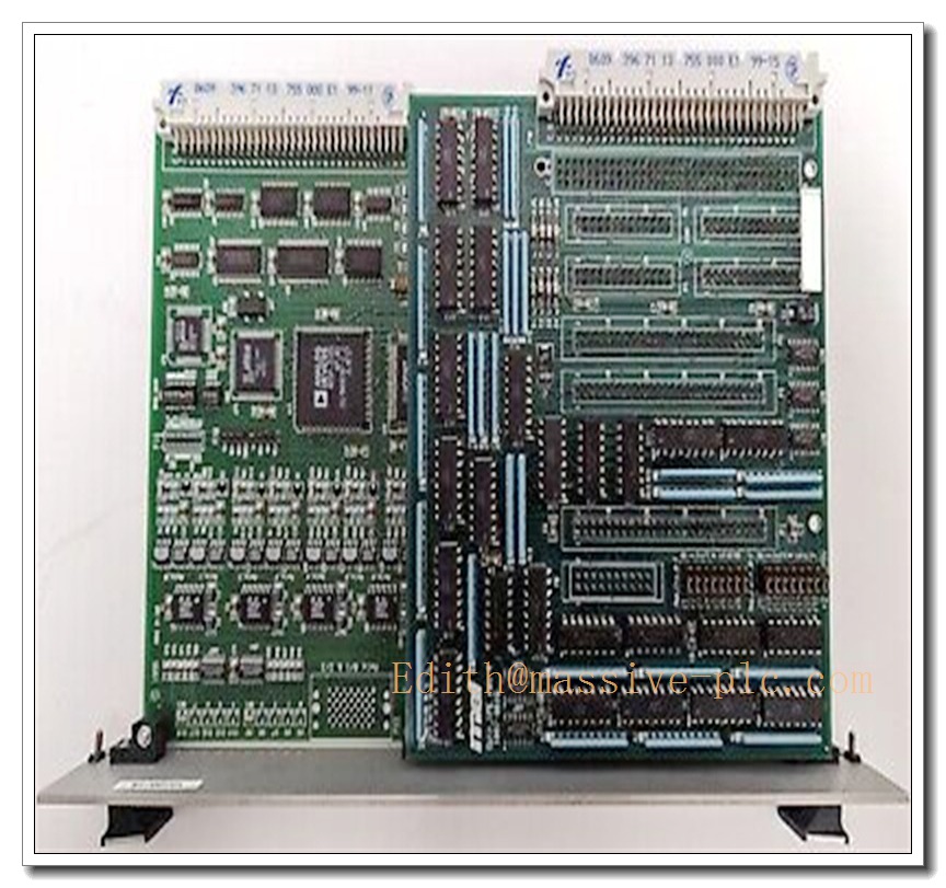
MEI 1007-0016 Motion Control Encoder Module
Product Description
The MEI 1007-0016 is a precision industrial motion control encoder interface module manufactured for high-speed position, velocity and motion feedback applications. It receives differential encoder signals from incremental encoders, resolves pulse data, and communicates position information to the motion controller in real time. Designed for high-accuracy positioning under continuous cyclic operation, this unit supports differential line driver inputs to resist electromagnetic interference in noisy factory environments. It is widely adopted in automated machinery that demands tight position tolerance, synchronous motion tracking and closed-loop motion control. The module performs signal decoding, edge capture and fault diagnosis for encoder wiring loss, signal loss and differential pair imbalance to safeguard motion sequences and prevent unexpected machine collision.
Technical Specifications
| Item | Parameter |
|---|---|
| Model | MEI 1007-0016 |
| Signal Input | Differential incremental encoder (A/B/Z phase) |
| Max Encoder Frequency | Up to 10 MHz pulse input |
| Input Type | RS-422 differential line receiver |
| Operating Temperature | 0°C ~ +60°C |
| Storage Temperature | -40°C ~ +85°C |
| Supply Voltage | 5 VDC / 24 VDC option |
| Channel Count | Multi-channel encoder acquisition |
| Communication Interface | Motion bus for host controller |
| Mounting Form | PCB card for industrial chassis slot installation |
| Environmental Rating | Designed for cabinet indoor use, non-condensing |
Compatibility & Installation Pitfalls
Compatibility
- Compatible with MEI motion control host boards and matching chassis backplane series.
- Works with standard RS-422 incremental encoders with A/B/Z differential outputs.
- Supports motion control software suites for parameter setup, position tuning and fault logging.
- Not compatible with single-ended TTL encoder signals without external signal conversion.
Common Installation Traps
- Mixing single-ended and differential encoder wiring will cause unstable position reading and lost pulses. Always use twisted-pair shielded cables for A/B/Z differential pairs.
- Incorrect backplane slot assignment can result in resource conflict, motion bus timeout or module recognition failure.
- Ground loop created by separate grounding points between encoder and control cabinet introduces heavy noise and position jitter.
- Exceeding maximum input pulse frequency leads to missed edges and inaccurate velocity feedback during high-speed cycles.
- Improper cable shielding termination: grounding shield at both ends induces circulating noise; only terminate shield at the cabinet controller side.
- Hot-swapping the module while the chassis power is active risks permanent damage to the input differential receivers and backplane circuits.
- Mismatched firmware revision between host motion controller and MEI 1007-0016 causes communication handshake failure.
- Overvoltage on encoder power supply burns the input protection circuit of the module.
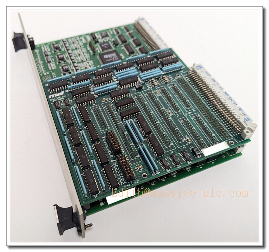
1007-0016 MEI
Standard Operating Procedure (SOP)
- Pre-inspection: Visually check the module for physical damage, burnt marks or bent gold fingers. Verify firmware revision matches the host motion controller.
- Power isolation: Cut off chassis and encoder power supply before inserting or removing the module. Wear an ESD wrist strap during handling.
- Chassis installation: Align the board with the guide rails, insert fully into the designated backplane slot and fasten the retention bracket.
- Wiring: Connect shielded differential encoder twisted pairs to the terminal header; separate encoder power cables from high-power servo motor cables.
- Power-up sequence: Enable cabinet chassis power first, then activate encoder field power. Wait for host controller to complete hardware enumeration.
- Software configuration: Launch motion configuration software, select the correct encoder type, set count direction, pulse scale and position limits.
- Functional test: Execute low-speed jog test, verify position tracking, index Z-phase capture and alarm response for wire break simulation.
- Commissioning and handover: Save parameter set to controller non-volatile memory; record calibration data and restore machine normal operation.
- Shutdown procedure: Stop all motion tasks, disable field power, then cut chassis power before disassembly or replacement.
Application Scenarios
- High-precision CNC machining equipment position feedback
- Automated pick-and-place and semiconductor handling machinery
- Printing, converting and web tension synchronous control systems
- Robotics joint position and velocity closed-loop control
- Packaging machinery multi-axis synchronous motion
- Gantry and linear motor positioning platforms
- Automated test equipment (ATE) motion measurement
- Laser cutting and precision positioning automation
Matching Components
- MEI industrial chassis and dedicated backplane
- RS-422 incremental encoders with A/B/Z differential output
- Twisted-pair shielded encoder signal cables
- Regulated 5 VDC / 24 VDC power supplies
- ESD protection wrist strap and anti-static mat
- Chassis slot retention brackets and mounting hardware
- MEI motion configuration software and programming toolkit
- Signal surge suppressors for encoder field circuits
Recommended Related Models (8)
- MEI 1007-0001
- MEI 1007-0004
- MEI 1007-0008
- MEI 1007-0012
- MEI 1007-0020
- MEI 1007-0024
- MEI 1007-0032
- MEI 1008-0002



 Start Chat




