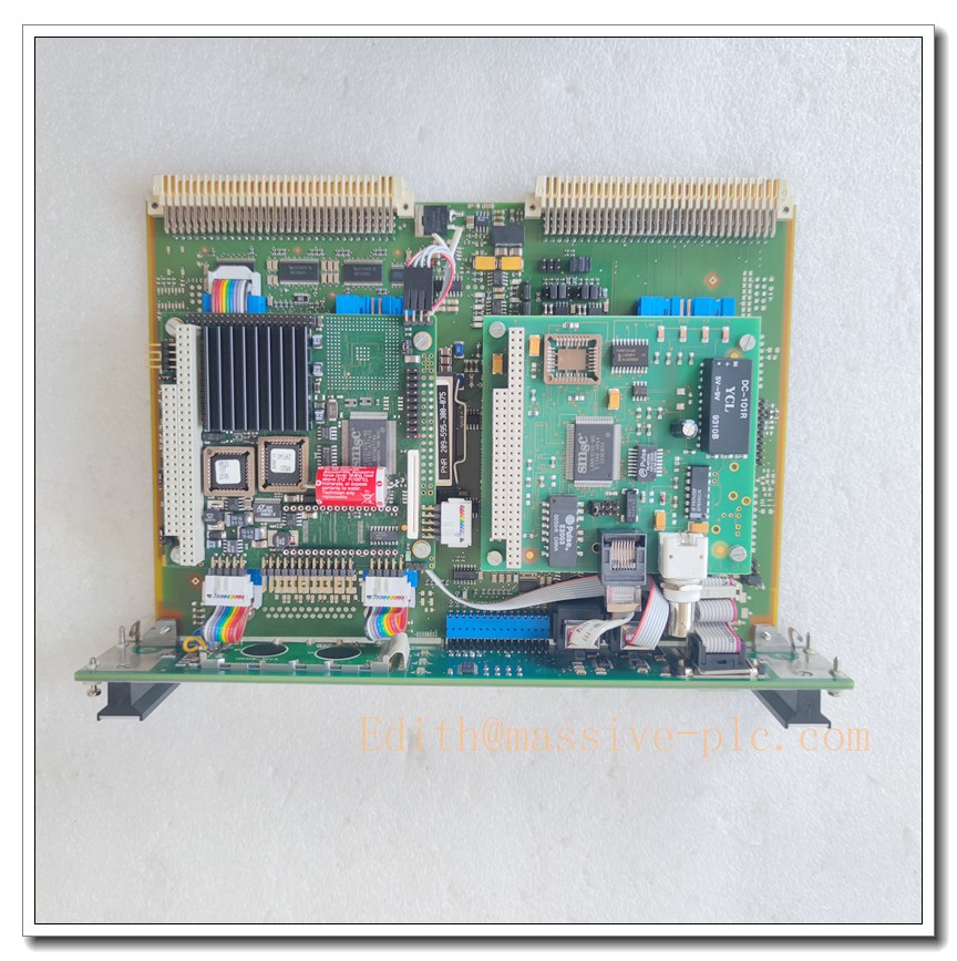
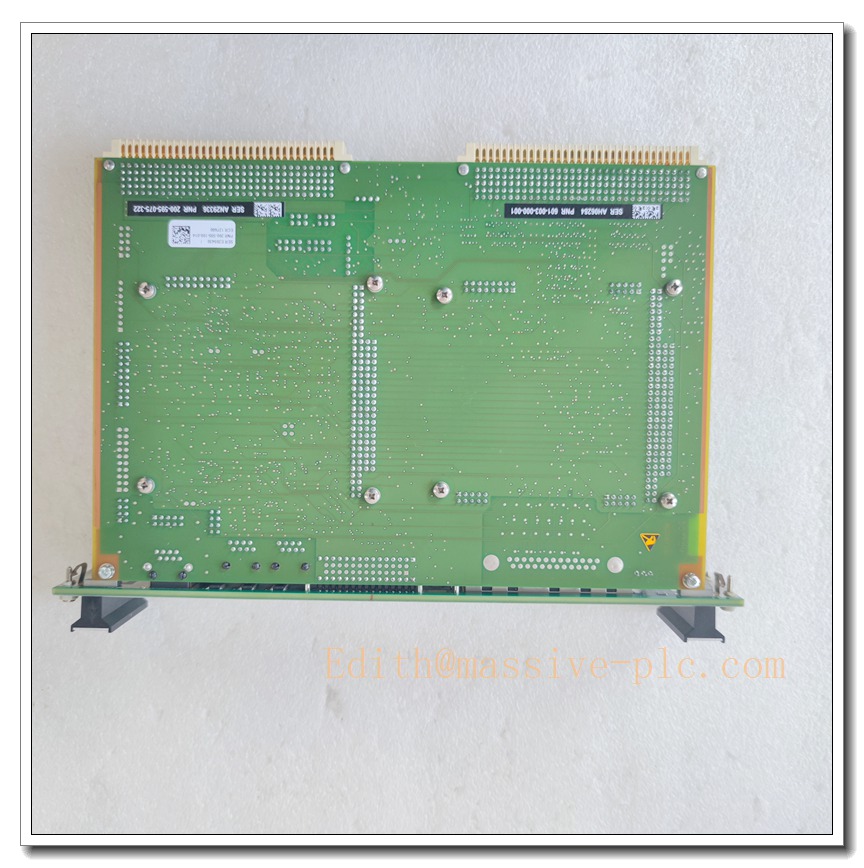
Description
Meggitt Vibro-Meter VM600 CPUM 200-595-100-013 / 200-595-0CS-12H Rack Central Processing Unit & Communication Gateway Card
Product Overview
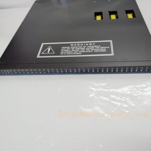
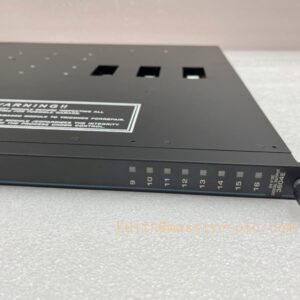
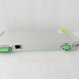
The Meggitt CPUM (CPU-M) is the primary rack controller and communication gateway for the VM600 machinery protection (MPS) and condition monitoring (CMS) system. The two variants 200-595-100-013 and 200-595-0CS-12H coordinate all plug-in modules inside the VM600 rack, including MPC4 protection cards, CMC16 monitoring cards, IOC I/O modules and relay cards. It collects real-time measurement data over the internal backplane bus, executes system-level alarm logic, manages event & transient waveform recording, and serves as the interface between the VM600 rack and external plant systems such as DCS, PLC, SCADA and operator workstations. The 200-595-0CS-12H is a customer-special firmware/configuration variant while 200-595-100-013 is the standard CPUM hardware revision. This module supports industrial fieldbus protocols and front-panel local operation for alarm reset and status viewing.
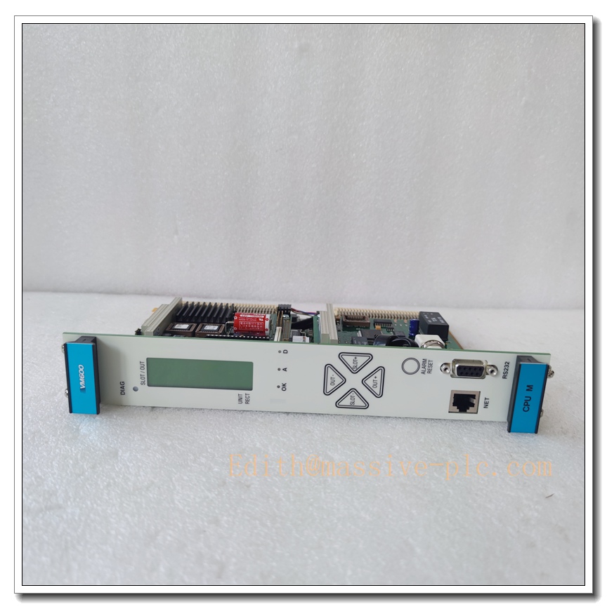
CPUM 200-595-077-331
Key Technical Specifications
- Part Numbers: 200-595-100-013, 200-595-0CS-12H
- Family: VM600 CPUM Modular CPU Card
- Processor: Embedded industrial CPU
- Memory: Onboard DRAM + non-volatile flash memory for firmware, configuration and event log storage
- Front Panel: LCD status display, multi-colour diagnostic LEDs, local alarm reset button, navigation keys
- Communication Ports
- Ethernet 10/100 Mbps (RJ45)
- Serial isolated ports: RS485 / RS232 / RS422
- Supported Protocols: Modbus TCP, Modbus RTU, PROFINET
- Backplane: VM600 internal rack bus for communication with MPC4, CMC16, IOC modules
- Power Supply: Powered by rack backplane, 24VDC rack power
- Operating Temperature: -20°C ~ +65°C
- Mechanical: 6U VME rack plug-in card
- Diagnostics: Continuous self-monitoring, module fault reporting, rack bus health check, configuration integrity verification
- Data Function: Event logging, trip transient data storage, system configuration management, time synchronisation
- Compliance: API 670, CE; SIL rating applies to full system only (not standalone CPUM)
- Hot-swap: Hardware supports hot swap; operational hot swap depends on system configuration and machine operating state
Recommended 8 Similar Series Models ( Family)
- Meggitt CPUM 200-595-074-122
- Meggitt CPUM 200-595-065-114
- Meggitt CPUM 200-595-033-111
- Meggitt CMC16 200-530-025-014 (your prior monitoring card)
- Meggitt MPC4 200-510-071-113 (your prior protection card)
- Meggitt IOC16T 200-512-160-001 I/O Card
- Meggitt RPS6U 200-504-001-001 Rack Power Supply
- Meggitt CPUM Mk2 (next-generation replacement for legacy CPUM)
Quality Control & Test Standard Operating Procedure (SOP)
- Visual Inspection: Inspect PCB, front panel, connectors, solder joints, labels and LCD screen. Confirm part number, hardware revision and marking match documentation; check for scratches, corrosion or bent pins.
- Continuity & Insulation Test: Pin-to-pin continuity verification; insulation resistance test between power circuits and signal interfaces to eliminate short-circuit risks.
- Power-Up Test: Apply rated rack power gradually. Verify power consumption stays within rated range, LED boot sequence completes normally, LCD powers up without display faults and no overheating occurs.
- Built-in Self-Diagnostic Test: Execute full CPUM internal self-test. Confirm no hardware fault codes, flash memory integrity pass and backplane controller initialisation successful.
- Firmware & Configuration Validation: Load matching firmware for the part variant. Verify parameter saving, configuration checksum and non-volatile memory retention after power cycle.
- Backplane Bus Communication Test: Install CPUM in rack, connect to simulated MPC4 / CMC16 modules. Validate stable data read/write between CPU and peripheral cards.
- Fieldbus Interface Test: Test Ethernet and serial ports. Validate Modbus TCP/RTU data read/write, protocol response, and correct timestamp transmission.
- Event & Alarm Function Test: Simulate rack alarm and trip events. Confirm event logging, waveform buffer capture, front-panel alarm reset function and timestamp accuracy.
- Environmental Burn-in Test: Continuous burn-in under rated operating temperature to screen early-life component failures.
- Final Recheck & Documentation: Repeat core functional tests after burn-in. Generate serial-number traceable test report before anti-static packing and shipment.
New Module Installation Guide
- Pre-Installation Preparation: Fully power down the rack. Wear ESD wrist strap and use anti-static work mat. Confirm part number, hardware revision and firmware variant match site BOM; confirm compatibility with existing rack modules.
- Rack Slot Inspection: Inspect target slot backplane connector for bent pins, dust or oxidation. Clean guide rails.
- Card Insertion: Align CPUM card with rack guide rails. Slide smoothly into slot until backplane connector fully mates. Tighten front panel retaining screws evenly.
- Pre-Power Configuration Check: Verify existing MPC4, CMC16 and IOC modules are correctly seated. Confirm rack wiring, shielding and earthing comply with wiring diagram.
- Power Restore: Energise rack power. Observe front panel LEDs and LCD screen to monitor boot progress. Wait until the system completes initial backplane discovery of all daughter cards.
- Commissioning & Firmware Setup: Connect MPS/CMS software. Upload valid system configuration file, match firmware version, set network parameters, fieldbus addresses and time synchronisation.
- Full System Functional Test: Run rack-wide self-test. Simulate alarm thresholds to verify data acquisition, alarm forwarding to DCS/SCADA, event logging and front panel indication.
- Post-Installation Documentation: Save validated configuration file, record serial numbers and commissioning test results.
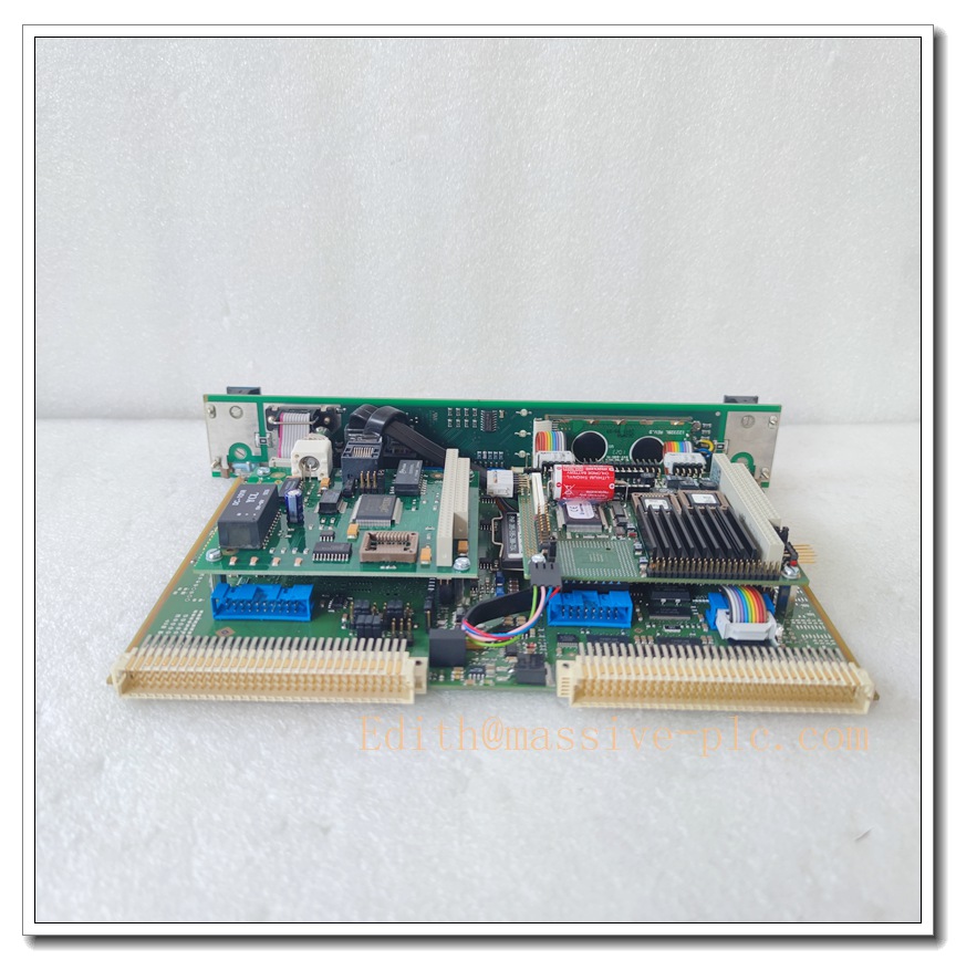
CPUM 200-595-077-331
Application Scenarios & Features
Application Scenarios
- Gas turbine and steam turbine machinery protection & condition monitoring racks
- Centrifugal and axial compressors in petrochemical, LNG and refinery plants
- Turbo-generator sets for power generation utilities
- Offshore rotating equipment monitoring systems
- Critical pumps, fans and gearboxes predictive maintenance & protection systems
- Plant-wide DCS/SCADA integration for turbomachinery
Core Features
- Central controller for full rack, orchestrating all MPC4 protection and CMC16 monitoring modules
- Internal backplane bus to aggregate vibration, speed, temperature and process measurement data
- Embedded event & transient waveform storage for machine trip and surge post-fault analysis
- Multiple industrial communication interfaces for connection to plant control systems
- Local front-panel LCD and alarm reset button for on-site operation and status review
- Non-volatile flash memory to retain system configuration and event logs through power loss
- Continuous hardware self-diagnostics for high system availability
- Seamless integration within complete machinery protection and monitoring ecosystem
FAQ
Q1: What is the difference between 200-595-100-013 and 200-595-0CS-12H?
A1: 200-595-100-013 is standard hardware CPUM. 200-595-0CS-12H is a custom special variant with customer-specific firmware and pre-defined configuration set. Always verify firmware compatibility and site BOM before replacement.
Q2: What is the role of CPUM compared to and ?
A2: CPUM = rack master controller and communication gateway. performs local protection measurements and relay trip logic. performs high-resolution vibration spectrum & waveform analysis. CPUM collects data from both card types, manages the whole rack and communicates to plant SCADA/DCS.
Q3: Can I hot-swap the CPUM card?
A3: Hardware supports hot insertion/removal. However, hot swap of the main rack controller will interrupt rack communication, event logging and external fieldbus data transmission. Hot swap is not recommended when protected machinery is running in critical operating state.
Q4: Is CPUM SIL2 certified?
A4: SIL certification belongs to the complete machinery protection system, not the standalone CPUM card. Full system safety assessment is required to achieve SIL level compliance.
Q5: What to do if rack modules are not discovered after CPUM replacement?
A5: Check backplane connector pins and seating of all cards. Confirm CPUM firmware version matches the compatible version for your existing / modules. Reload valid system configuration and run full rack self-test.
Q6: What communication protocols are supported?
A6: Modbus TCP over Ethernet, Modbus RTU over RS485, and PROFINET. Serial ports also support RS232 for local diagnostic connection.
Q7: Where are system configuration files stored?
A7: Configuration files are saved inside CPUM non-volatile flash memory. Always back up the valid configuration before replacing CPUM.
Q8: Is this CPUM still in production?
A8: Legacy Mk1 CPUM series is discontinued by Meggitt. Spare units are for maintenance replacement only; CPUM Mk2 is the newer generation alternative for new projects.