
Description
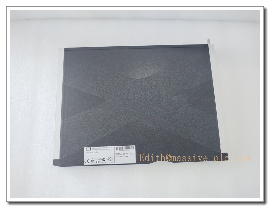
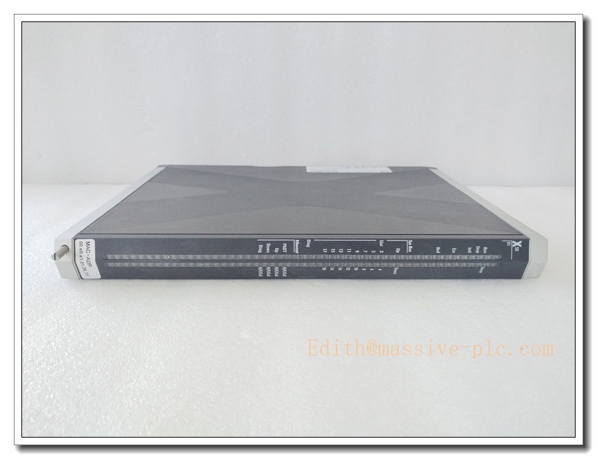
HIMA X-SB01 (Item No.985210207) HIMax System Bus Module
Core Product Overview
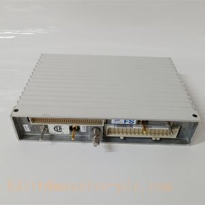
X-SB01 985210207 is the HIMax rack-level system bus module from HIMA. It serves as the high-integrity backplane communication backbone inside the HIMax safety rack, responsible for real-time data exchange between F8650X safety CPUs, power modules and all HIMax I/O cards. It supports both mono and redundant bus operation, with built-in diagnostic functions for bus faults, link loss and module health monitoring. Configuration and diagnosis are performed via SILworX. It is TÜV-certified for SIL 3 (IEC 61508 / IEC 61511) and is widely used in ESD, FGS and HIPPS systems for oil & gas, chemical and power plants.
Main Technical Specifications
- Part Number: X-SB01, HIMA Item No. 985210207
- Manufacturer: HIMA Paul Hildebrandt (Germany)
- Device Type: HIMax System Bus Module
- Safety Certification: TÜV, SIL 3
- Interfaces: 2×System Bus (Up/Down), 1×PADT service port, 1×Diagnostic port
- Status LEDs: Run, Error, Stop, Init, Redundancy, Rack link status
- Supply: 24 VDC, approx. 0.65 A
- Cooling: Passive, relies on rack forced airflow
- Operating Temperature: -20°C ~ +60°C
- Humidity: 10%–95% non-condensing
- Protection: IP20
- Form Factor: HIMax Eurocard plug-in rack module
- Status: Active supported HIMax component; spare stock available as new surplus or professionally refurbished bench-tested units
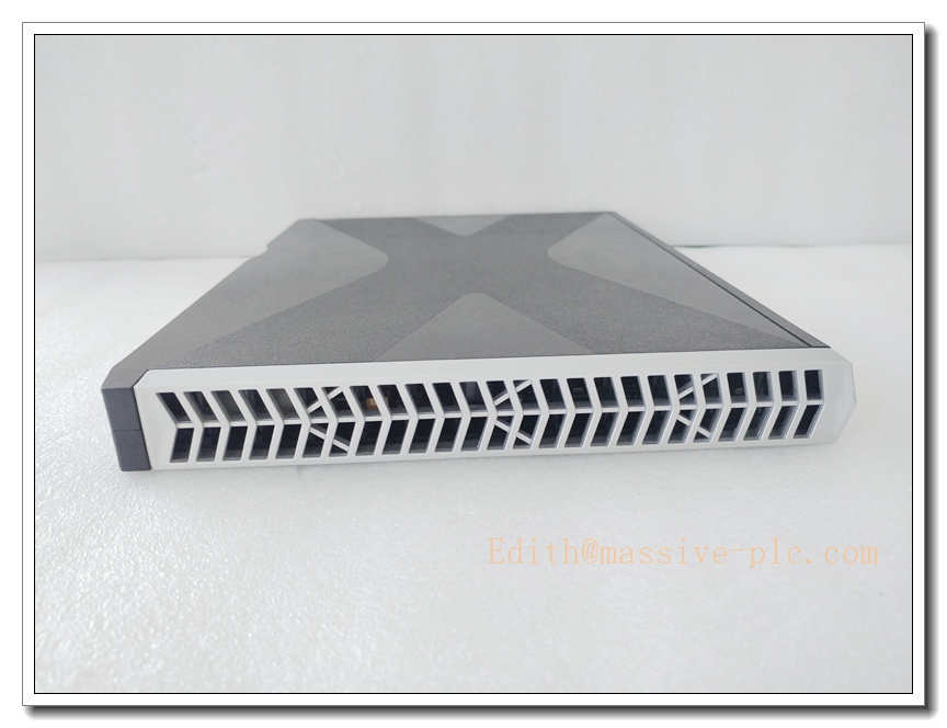
X-SB01 985210207
Same-Series Model Recommendations (8 Models)
- X-SB01 985210207: HIMax system bus module (subject model)
- F8650X 984865065: HIMax main safety CPU
- F8627X: HIMax communication co-processor
- F8651X: HIMax redundant power supply
- F8621A: HIMax SafeEthernet communication module
- X-DI01: HIMax digital input module
- X-DO01: HIMax digital output module
- F-CPU01: HIQuad X generation safety CPU
Professional Quality Control & Testing Standard Operating Procedures
All surplus and refurbished X-SB01 985210207 modules follow this inspection workflow:
- Visual Inspection: Inspect PCB, edge fingers, front-panel LEDs, capacitors and solder joints; verify part number, item code 985210207 and TÜV safety label.
- Backplane Power Bench Test: Install in HIMax compatible backplane, apply 24VDC, verify stable power rails, no overcurrent or cycling.
- Boot & Firmware Validation: Complete power-on self-test, read firmware revision, confirm no permanent hardware fault codes.
- System Bus Link Test: Daisy-chain multiple X-SB01 modules, validate up/down bus communication and redundancy switchover.
- PADT & Diagnostic Port Test: Connect via SILworX, confirm module identification, bus status and fault reporting.
- Rack Communication Test: Pair with F8650X CPU and HIMax I/O modules, verify cyclic safety data exchange.
- Thermal Soak Test: Run module at elevated cabinet temperature to expose intermittent connector or timing faults.
- Final Cleaning & Packaging: Clean edge contacts, reset configuration, ESD packaging with printed test certificate.
New / Refurbished Module Installation Guidelines
- Pre-Installation Safety: Execute lockout-tagout; isolate HIMax rack 24V supply and all field safety circuits to prevent spurious SIS trips.
- Rack & Backplane Check: Confirm HIMax dedicated backplane, protective earth, cabinet cooling fan and ventilation clearance.
- Mechanical Insertion: Align the X- edge connector carefully with the backplane, insert smoothly without force, secure front panel screws.
- Bus Wiring: Terminate the up/down system bus links between X- modules; use specified shielded cables and proper grounding.
- System Configuration: Use SILworX to define rack topology, bus redundancy mode and module assignment.
- Pre-Commissioning Functional Test: Power rack offline; verify bus status LEDs, fault detection for broken bus links and SILworX online diagnosis.
- Safety Acceptance: Test redundant bus switchover, confirm CPU and I/O communication remains intact during single bus fault; archive SILworX project.
Application Scenarios & Product Features
Typical Application Scenarios
- Emergency Shutdown System (ESD) for refineries, chemical plants and offshore platforms
- Fire and Gas System (FGS) gas/flame detection interlocks
- High Integrity Pressure Protection System (HIPPS)
- Burner Management System (BMS) for gas turbines and boilers
- Power plant critical safety interlock racks
- Spare replacement and retrofit for existing HIMax SIS racks
Core Product Features
- SIL 3 certified system bus for HIMax safety racks
- Supports mono or redundant bus topology to improve rack availability
- Dedicated Up/Down system bus ports for rack daisy-chain expansion
- PADT service port for local SILworX connection and maintenance
- Comprehensive bus diagnostics with front-panel LED indication
- Deterministic cyclic data exchange between HIMax CPU and I/O modules
- Hot-swap capable (with proper SIS bypass procedures)
- Robust EMC design for noisy process control cabinets
Frequently Asked Questions (FAQ)
A1: It is the internal rack system bus. It does not execute safety logic; it transports safety data between F8650X CPU, power supplies and I/O modules.
A2: No. X- belongs exclusively to the HIMax platform and is not compatible with HIQuad X hardware.
A3: Hardware supports hot swap, but removal while online may break rack bus communication and trigger SIS trips. Always apply approved bypass before replacement.
A4: SILworX. You can connect to the PADT port for module status, bus health and fault diagnostics.
Q5: What are common failure modes? A5: Edge connector oxidation, bus port damage from ESD, ageing capacitors, firmware corruption caused by voltage transients, LED degradation.


 Start Chat




