
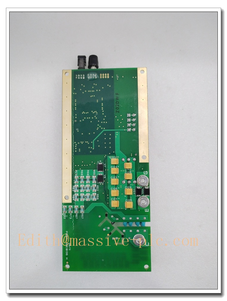
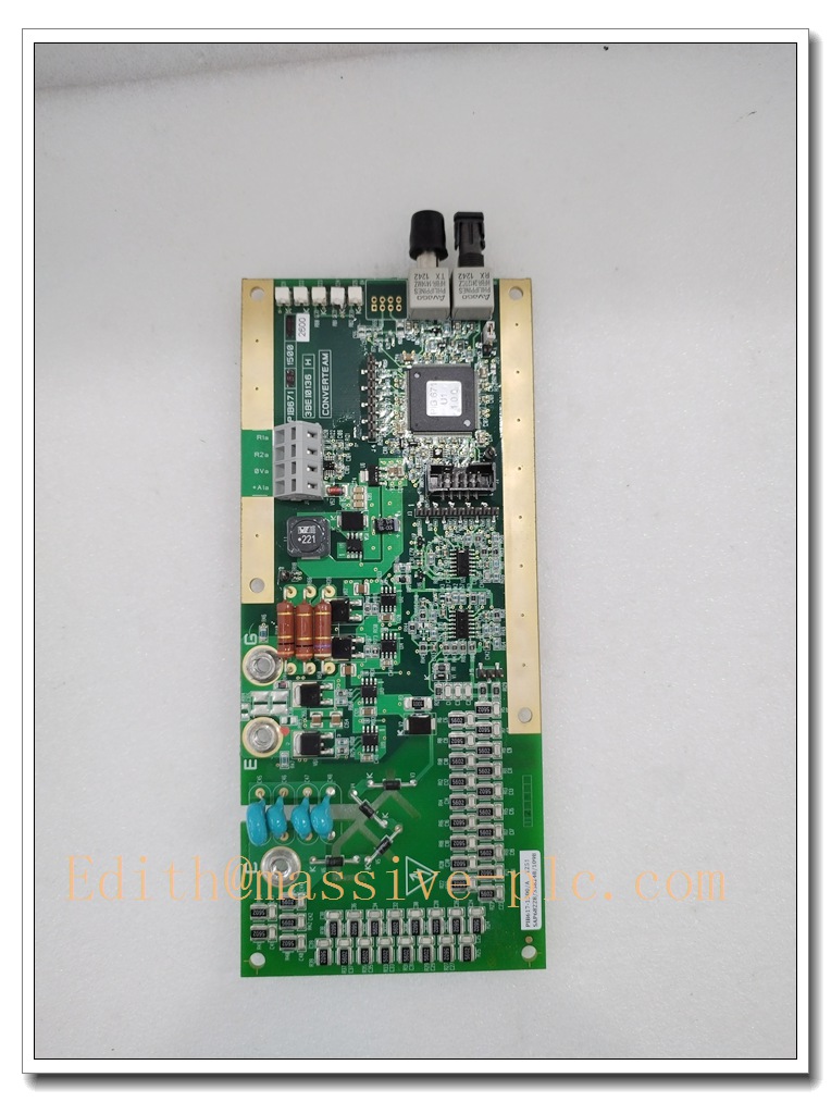
Description
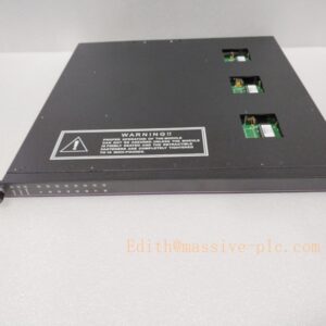
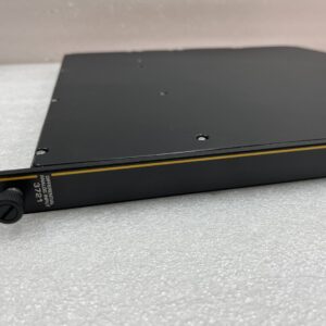
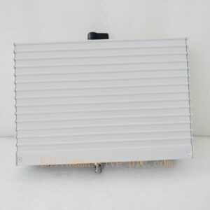
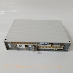
CONVERTEAM PIB671-1500 High Power IGBT Power Interface Board
Product Core Introduction
The PIB671-1500 is a high-power power interface board manufactured by CONVERTEAM (formerly ALSTOM, later acquired by Siemens/GE). It is a core power stage interface component for the ALSPA MV3000 medium voltage variable speed drive system. This board acts as the critical bridge between low-voltage control logic and high-power IGBT power cells. It delivers IGBT gate drive signals, executes real-time power stage monitoring, and triggers rapid hardware protection upon faults. With robust gate drive circuits and integrated thermal & current sensing, it synchronizes multi-level power cell operation, suppresses harmonic distortion, and ensures safe and stable operation for large medium-voltage motor drives in heavy-duty industrial sites.
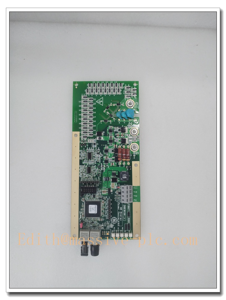
PIB671-1500
Main Technical Specifications
| Item | Parameter |
|---|---|
| Manufacturer | CONVERTEAM (Alstom legacy) |
| Model | PIB671-1500 |
| Module Type | IGBT Power Interface / Gate Drive Board |
| Compatible Drive | ALSPA MV3000 Medium Voltage VFD |
| Rated Continuous Current | 1500A |
| Peak Current | 3000A (10s) |
| Max AC Voltage Rating | 690V AC |
| Power Handling | Up to 1.5MVA |
| Communication | Backplane parallel bus; Modbus RTU / Modbus TCP for diagnostic data |
| Cooling | Liquid cooling (water-glycol), integrated flow sensor |
| Operating Ambient Temp | -10℃ ~ +55℃; derated up to +70℃ |
| Storage Temperature | -40℃ ~ +85℃ |
| Protection | Overcurrent, overvoltage, undervoltage, short-circuit crowbar, overtemperature shutdown |
| Certification | CE, IEC 61800 adjustable speed power drive standard |
| Mounting | Subrack slot mount for MV drive cabinet |
| Protection Class | IP20 (board inside sealed cabinet IP54) |
Brand Same Series Model Recommendation
- PIB671-0800: 800A mid-range power interface board for smaller MV drive cells
- PIB671-1200: 1200A version for medium power motor loads
- PIB671-1500: 1500A high-current model for large heavy-duty motors
- PIB671-2000: 2000A upgraded high-current variant for ultra-large power conversion units
Professional Quality Control Test Standard SOP
- Visual Inspection: Inspect PCB traces, soldering, connectors, capacitors and labels for corrosion, cracks or component damage.
- Power-on Low-Voltage Test: Apply low control supply voltage, verify power LED status and no short circuit.
- Gate Drive Signal Test: Check IGBT gate pulse amplitude, timing and synchronization for all channels.
- Protection Function Test: Simulate overcurrent, overtemperature and short-circuit conditions to verify fast trip response.
- Communication & Backplane Test: Insert into drive rack, validate diagnostic data transmission to main controller.
- High Voltage Withstand Test: Perform hipot test between power circuit and control circuit per IEC61800.
- Thermal Cycling Test: -40℃ to +70℃ temperature cycling for 24 hours to validate thermal stability.
- Vibration Screening Test: Simulate cabinet vibration conditions to check solder joint reliability.
- Full Load Burn-in Test: 72 hours continuous burn-in under rated load, record fault logs before packaging.
New Module Installation
- Isolate all high voltage power supply of the medium voltage drive cabinet. Lock out / tag out (LOTO) procedure must be followed. Wear anti-static wristband.
- Verify part number PIB671-1500 matches drive BOM and power cell configuration.
- Remove the cabinet cover and liquid cooling pipe connections carefully. Release locking levers and extract the old board.
- Insert new PIB671-1500 board into the designated slot, lock front panel fasteners securely.
- Reconnect liquid cooling pipelines, check for coolant leakage; reconnect backplane bus and gate drive wiring strictly following wiring diagram.
- Inspect all wiring terminals, confirm no loose terminals or miswiring.
- Restore cabinet covers, close LOTO, power on control supply first. Run drive self-diagnosis.
- Perform dry-run test without high voltage, validate gate pulse and fault diagnostics. Then carry out low-load commissioning before full-load operation.
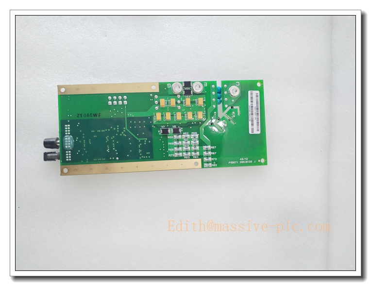
PIB671-1500
Application Scenarios & Features
Application Scenarios
- Medium voltage variable speed drives for large industrial motors
- Power plant large boiler feed pumps, induced draft fans
- Oil & gas large compressor motor drives
- Metallurgical rolling mill main drive systems
- Marine heavy propulsion power conversion systems
Features
✅ High-current IGBT gate driving & real-time power cell monitoring for MV multi-level converters ✅ Integrated multi-hardware protection: overcurrent, short-circuit, over-temperature with ultra-fast response ✅ Liquid cooling design for high continuous current capacity and stable thermal performance ✅ Synchronized multi-cell control to reduce harmonic distortion and improve motor efficiency ✅ Backplane diagnostic interface for real-time board health status monitoring ✅ Rugged PCB design, suitable for power plant, petrochemical and metallurgy heavy vibration environments ✅ Drop-in replacement for ALSPA MV3000 series medium voltage drives
FAQ
A: No. High voltage cabinet power must be fully isolated and LOTO performed before replacement. Hot swap is NOT permitted for safety reasons.
Q2: Drive reports IGBT gate fault after board replacement, what to check? A: Check gate drive wiring, backplane connector seating, coolant flow and grounding. Verify firmware compatibility with the main drive controller.
A: PIB671-1200 is rated for 1200A continuous; supports higher continuous 1500A current for larger power cells.
Q4: Is it compatible with other brands of MV drives besides ALSPA MV3000? A: No, it is designed exclusively for CONVERTEAM ALSPA MV3000 drive architecture. It cannot be used for other vendor VFD systems.
Q5: Coolant leakage alarm triggered after installation? A: Inspect pipe fittings, seals and hose connections. Check coolant flow sensor wiring and sensor calibration.

 Start Chat




