
Description
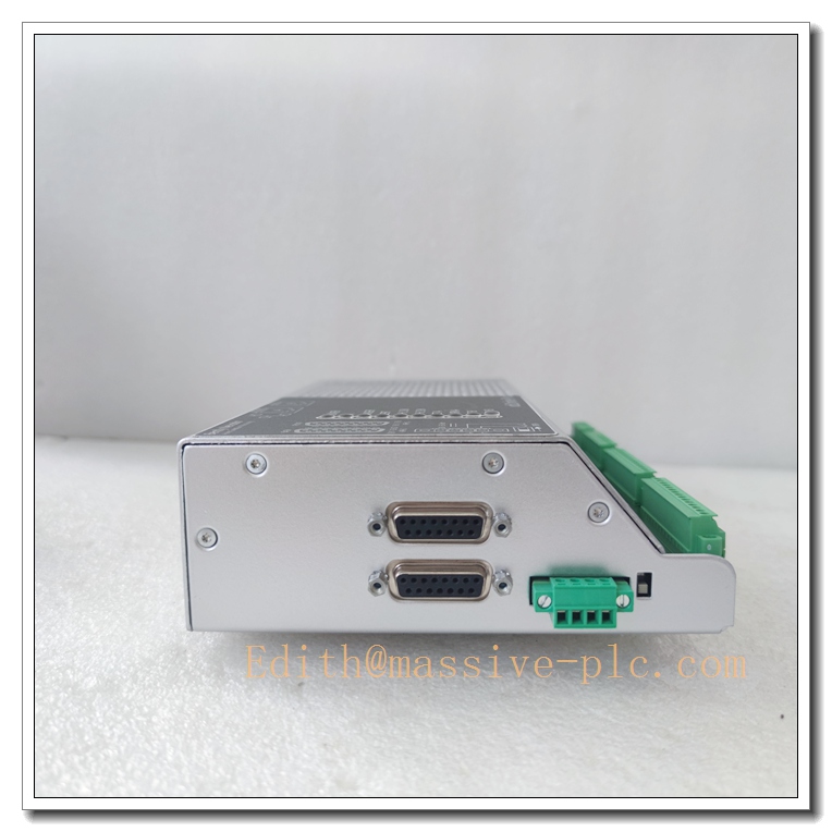
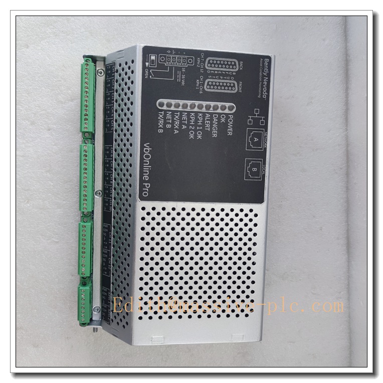
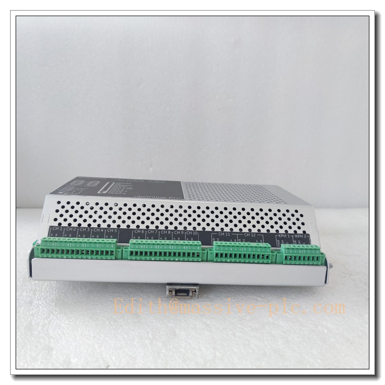
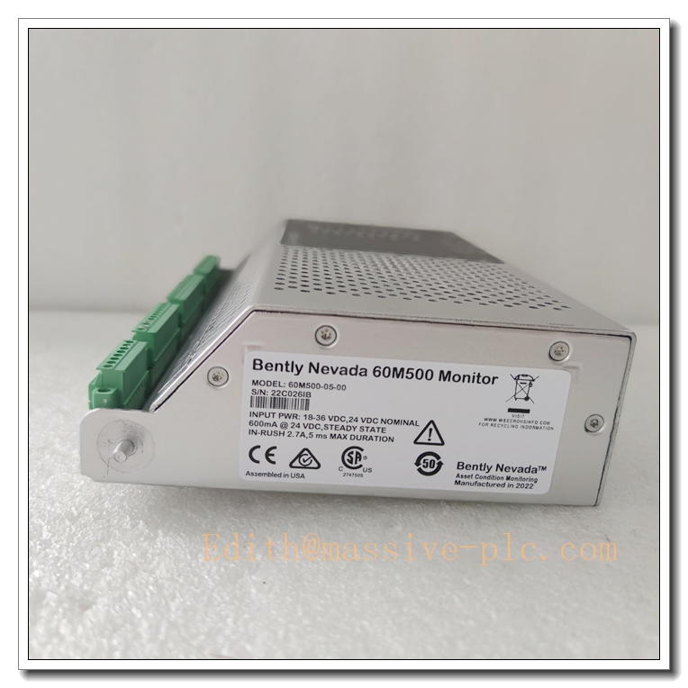
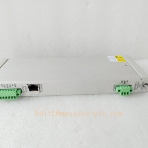
Bently Nevada 60M500-05-00 vbOnline Pro Online Condition Monitoring Unit
Product Core Introduction
The 60M500-05-00 is the vbOnline Pro compact online condition monitor from Bently Nevada (Baker Hughes). It is a DIN rail mounted multi-channel data acquisition unit for continuous rotating machinery health monitoring. It accepts vibration transducer inputs (accelerometer, velocity sensor, proximity probe), RTD temperature and tachometer speed signals, performs real-time spectrum analysis, trending and fault diagnostics. It can communicate with Bently System 1 predictive maintenance software and plant DCS/PLC via Ethernet Modbus TCP. It is designed for auxiliary and non-critical rotating assets to detect imbalance, misalignment, bearing faults and gear damage at an early stage. This unit is widely used for pumps, fans, compressors and gearboxes. OEM active product; new and fully tested refurbished spare stock available.
60M500-05-00
Main Technical Specifications
| Technical Parameter | Specification Value |
|---|---|
| Model | 60M500-05-00 (Bently Nevada) |
| Series | vbOnline Pro |
| Product Type | Online machinery condition monitor |
| Analog Input Channels | 12 dynamic vibration channels |
| Additional Inputs | RTD temperature, tachometer speed input |
| A/D Conversion | 24-bit sigma-delta ADC |
| Frequency Range | 0.5 Hz ~ 10 kHz |
| Communication | Ethernet, Modbus TCP, compatible with System 1 software |
| Local Storage | Onboard memory + SD card slot for historical data logging |
| Power Supply | 24 VDC ±10% |
| Mounting | DIN rail mounting |
| Operating Temperature | -40 ℃ ~ +70 ℃ |
| Storage Temperature | -45 ℃ ~ +85 ℃ |
| Operating Humidity | 0 ~ 95% RH, non-condensing |
| Dimensions | 225 × 150 × 55 mm |
| Net Weight | ~1.4 kg |
| Compliance | CE, RoHS, ATEX / IECEx optional |
| Lifecycle Status | Active product, new & refurbished spare available |
Brand Same‑Series Model Recommendation
- 60M500-04-00: Lower channel variant, fewer analog inputs for simple vibration monitoring.
- 60M500-06-00: Enhanced version with additional relay alarm outputs.
- 1900 series: Standalone panel mount machinery protection monitor, for simple alarm & trip.
- 3500 rack system: Rack-based high-end protection system for critical turbo machinery.
Professional Quality Control Test Standard Operating Procedures (SOP)
5.1 Incoming & Visual Inspection
Inspect PCB, terminal blocks, Ethernet port, SD card slot, power circuit and enclosure. Visual check for PCB damage, burnt traces, connector oxidation and casing cracks. Continuity test for all signal terminals. Retain batch traceability records.
5.2 Low-Voltage Power-On Pre-Test
Apply 24VDC power. Verify power LED boot, network initialization, SD card detection. Check network handshake to PC / System1 software. Check for abnormal heating.
5.3 Burn-in Test
48-hour continuous powered burn-in at 40°C ambient. Inject simulated vibration, tachometer and RTD signals. Verify channel reading stability, spectrum calculation, data logging and alarm triggering. Reject units with intermittent communication or signal drift.
5.4 Full Functional Calibration & Parameter Test
Use signal simulator to inject vibration and temperature signals for all channels. Calibrate transducer sensitivity, sampling and spectrum analysis. Validate Modbus TCP communication, data trending and fault alarm thresholds. Test SD card data storage and export function.
5.5 Environmental Stress Screening
Temperature cycling (-40 ℃ ↔ +70 ℃), humidity soak and low-level vibration per IEC 60068. Recheck measurement accuracy and network communication after stress screening.
5.6 Final Acceptance Test
Full integration test with System1 software. Verify real-time waveform, FFT spectrum, trend log and remote configuration. Complete appearance, label and accessory inspection before anti-static packaging.
60M500-05-00
New Unit Installation Guidelines
6.1 Pre-Installation Preparation
- Lock-out/tag-out sensor and monitor power supply.
- Wear anti-static wristband and gloves.
- Inspect 60M500-05-00 for casing damage, terminal deformation. Confirm transducer type and System1 software compatibility.
- Prepare DIN rail, shielded sensor cables, Ethernet network cable.
6.2 Hardware Installation
- Snap the unit onto DIN rail inside control cabinet.
- Wire vibration sensors, RTD, tachometer, 24VDC power supply, strictly following Bently wiring diagram.
- Connect Ethernet port to plant network / System1 server.
- Separate low-level sensor cables from high-power motor cables to reduce EMI interference. Ensure good protective earth grounding.
6.3 Post-Installation Commissioning
- Double-check wiring, grounding and cable connections before power-on.
- Power up the unit, confirm power LED and network status.
- Configure transducer type, sensitivity, sampling parameters and alarm thresholds via software.
- Perform static signal test to verify channel readings and spectrum quality.
- Connect field sensors, run machine continuous trending test for 30–60 minutes before putting into online condition monitoring.
Important Safety Note: This unit is for condition monitoring (predictive maintenance), NOT machinery protection trip. It does not provide safety trip relay for critical turbine/generator protection. Only certified vibration monitoring technicians are allowed for configuration and commissioning.
Application Scenarios & Product Characteristics
7.1 Application Scenarios
- Power plant auxiliary pumps, fans, blowers
- Petrochemical & refinery compressors, gearboxes
- Mining, pulp & paper, water treatment rotating equipment
- General manufacturing motors and gear units
- Predictive maintenance online vibration monitoring, asset health trending
7.2 Key Characteristics
- Compact DIN rail design for cabinet installation
- 12 dynamic vibration input channels, supports multiple transducer types
- High-resolution 24-bit ADC, real-time FFT spectrum analysis
- Built-in tachometer and RTD temperature measurement
- Onboard + SD card historical data logging
- Ethernet Modbus TCP, native integration with Bently System1 software
- Wide temperature range for harsh industrial environments
- For predictive condition monitoring (not safety protection trip)
60M500-05-00
FAQ (Frequently Asked Questions)
Q1: No communication between vbOnline Pro and System1 software. A1: Check Ethernet cable, IP address setting, network firewall. Confirm device firmware compatibility. Reboot unit and retry connection.
Q2: Vibration channel reading unstable, noisy signal. A2: Check shield grounding of sensor cable, transducer installation. Verify cable routing away from high-voltage power lines.
Q3: SD card cannot record historical data. A3: Check SD card format and card seating. Verify data logging function enabled in configuration software.
Q4: Can I use this unit for turbine protection trip? A4: No. vbOnline Pro is for condition monitoring only. For machinery protection with trip relays, use Bently 3500 or 1900 series.
Q5: Can I replace 60M500-05-00 with 60M500-06-00 directly? A5: Hardware form factor is compatible, but I/O function and firmware differ. Reconfigure parameters and validate alarms after replacement.
Q6: Hot swap allowed? A6: Not recommended. Power off 24VDC supply before wiring modification to avoid ESD damage.


 Start Chat




