
Description
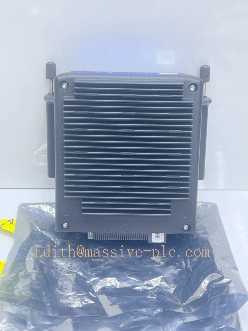
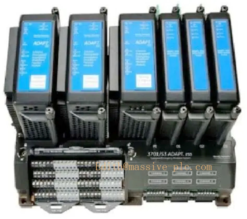
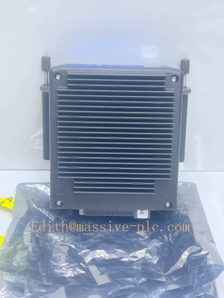
Bently Nevada 3701/44 ADAPT Aeroderivative Monitor
Model Introduction
Model: 3701/44 Aero‑Derivative Gas Turbine Monitor Part Number:3701/44 (Simplex / Duplex redundant base options) Device Type: High‑performance condition‑monitoring & protection unit of ADAPT‑3701 platform, dedicated for aeroderivative gas turbinesBaker Hugh…. Manufacturer: Bently Nevada (Baker Hughes)
System Compatibility: ‑ Available in Simplex (single‑processor) or Duplex (dual‑redundant processor) terminal base configuration. ‑ Input modules: PAA / PAV / PoV input cards; supports proximitor probe, IEPE accelerometer, velocity transducer, dynamic pressure sensor, keyphasor/speed input. ‑ Configuration via BNMC (Bently Nevada Monitor Configuration) software; data interface to System‑1 Evolution; Modbus‑TCP / RTU for DCS/SCADA integrationBaker Hugh…. ‑ Not 3500 rack card; not safety TMR‑ESD (3701/55 is for safety overspeed trip).
Application Scenarios: Aeroderivative gas turbines: GE LM2500, LM6000, LM1600; Rolls‑Royce RB211; Pratt & Whitney FT4 / FT8 and driven compressors/generatorsBaker Hugh…. Measures shaft radial vibration, thrust position, casing absolute vibration, combustion dynamic pressure pulsation; provides machinery protection alarm + condition‑based monitoring with order‑tracking filters for multi‑rotor‑speed gas turbine unitsBaker Hugh…. Country of Origin: United States Lifecycle Status: Active production, new & spare parts available.
Important note: ‑ 3701/44 optimised for aero‑gas‑turbine special algorithm: multi‑speed tracking filter, high‑order narrow‑band bandpass filter, dynamic combustion pressure measurement. ‑ Duplex version uses dual processor modules for higher reliability; simplex for general‑purpose skid‑mount installation. ‑ For safety overspeed trip function, deploy separate 3701/55 TMR‑ESD unit; 3701/44 is monitor only, not safety trip controller.
BENTLY 370144
Technical Introduction
Core Functions
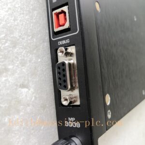
‑ Multi‑channel sensor input: proximity probe, IEPE accelerometer, velocity sensor, dynamic pressure transducer, keyphasor / speed signal. ‑ Aero‑turbine dedicated signal processing: rotor‑speed tracking filter, high‑order narrow‑band filter, multi‑bandpass filtering on single input channel, combustion pulsation pressure analysisBaker Hugh…. ‑ Measure shaft radial displacement, thrust position, casing absolute vibration, dynamic pressure; support FFT spectrum, time‑waveform recording, order‑tracking data for variable‑speed operation. ‑ Per‑channel independent Alert / Danger alarm thresholds, configurable alarm delay, latching / non‑latching relay logic. ‑ Built‑in comprehensive transducer fault detection (open‑circuit / short‑circuit). ‑ Relay output module for alarm annunciation & protection interlock. ‑ Large‑capacity event log & waveform storage for post‑trip failure analysis. ‑ Communication: Dual Ethernet, RS485 Modbus TCP/RTU; compatible with System‑1 Evolution asset management software. ‑ USB service port for BNMC software configuration & local diagnosis.
Key Technical Specifications
| Item | Parameter |
|---|---|
| System architecture | Simplex or Duplex dual‑redundant processor base |
| Sensor interfaces | Proximitor, IEPE accelerometer, Velomitor, dynamic pressure, Keyphasor/speed |
| Special algorithm | Tracking filter, high‑order narrow‑band filter, combustion pressure pulsation measurement |
| Relay output | Relay module, SPDT dry‑contact relays |
| Communication | Dual Ethernet(Modbus‑TCP), RS485(Modbus‑RTU), USB service port |
| Power supply | 18‑36 VDC |
| Operating temperature | ‑40 ℃ ~ +70 ℃ |
| Storage temperature | ‑45 ℃ ~ +85 ℃ |
| Humidity | 0‑95 % non‑condensing |
| Compliance | API‑670, CE, FCC, industrial EMC standards |
Mechanical Feature
Compact modular ADAPT‑3701 chassis, skid‑mount / cabinet‑mount installation. Composed of terminal base, processor module, input modules, relay output module. Field wiring terminates on base terminal blocks. Partial modules support hot‑swap under specified maintenance conditions.
Adaptive Quality Assurance & Test Protocol
3.1 Factory Adaptive QA Procedure
- Power‑on full‑unit self‑diagnostic verification.
- Sensor signal injection test: proximitor, accelerometer, dynamic pressure, keyphasor speed input; verify measurement accuracy and tracking‑filter algorithm performance.
- Alarm threshold, time‑delay, relay logic test.
- Transducer fault simulation test (open / short circuit).
- Waveform capture, event‑log recording verification.
- Modbus‑TCP / RTU & System‑1 communication interoperability test.
- Environmental screening: temperature cycling, vibration & shock test, EMC noise‑immunity test.
- Serial‑number traceability, full functional‑test report archived.
3.2 On‑site Acceptance Test Protocol
- Visual inspection: Check chassis, processor / input / relay modules, terminal blocks for mechanical damage. Confirm simplex / duplex hardware configuration matches project requirement.
- Wiring check: Transducer sensors, 24VDC power supply, relay interlock wiring, Modbus communication wiring.
- Power‑on test, confirm self‑test completes without hardware fault.
- Connect PC via USB port, download site configuration project by BNMC software; set channel parameters, tracking‑filter parameters, alarm thresholds, relay logic.
- Inject simulated sensor signals channel‑by‑channel; verify measured value, alarm trigger, relay output, waveform recording.
- Cross‑check remote data via Modbus‑TCP/RTU on DCS / System‑1 side.
- Simulate sensor open‑circuit / short‑circuit fault, verify fault‑alarm response.
- Record part‑number, hardware revision, firmware version, simplex/duplex type and backup project file for site QA archive.
Field Engineer Technical Notes
Installation Guidance
‑ Install in control cabinet or unit skid; ensure sufficient ventilation. ‑ Sensor cables must be shielded; separate from high‑voltage / VFD power cables; single‑end grounding to minimise EMI interference. ‑ Confirm ordering configuration: Simplex vs Duplex base, input module type (PAA / PAV / PoV) before spare‑part purchase. ‑ 3701/44 is monitoring‑protection unit; safety overspeed trip shall be implemented by separate 3701/55 TMR‑ESD system.
Field note: Duplex dual‑processor base improves availability for critical aero‑turbine sites; simplex for general skid‑mount auxiliary‑driven equipment.
Commissioning Tips
‑ All channel setup, tracking‑filter parameters, alarm logic are downloaded from BNMC software; keep secure backup of project source file. ‑ Optimise tracking‑filter parameters for multi‑rotor‑speed operating conditions of aeroderivative gas turbine to avoid false alarms. ‑ Cross‑validate: unit local reading shall be consistent with DCS and System‑1 remote reading.
Troubleshooting Common Issues
- System fault alarm: Read detailed diagnostic information via BNMC configuration software.
- Channel transducer fault: Inspect sensor and field cable for open‑circuit / short‑circuit.
- Modbus communication loss: Verify IP address / baud‑rate, slave address, bus termination resistor.
Diagnostic: Review unit event log and stored waveform data via BNMC for detailed fault analysis.
Maintenance & Spare‑part Recommendation
‑ Spare‑part suggestion: Keep matched spare processor / input / relay modules; spare firmware version must match on‑site running version. ‑ Preventive inspection during shutdown: Check module locking status, terminal‑block torque, cable shielding integrity.
ADAPT‑3701 platform product comparison table
| Part Number | Product name | Target equipment | Core feature |
|---|---|---|---|
| 3701/40 | MDM Machinery Dynamics Monitor | General critical rotating machinery | Universal vibration & position monitor |
| 3701/44 | Aero‑Derivative Monitor | Aeroderivative gas turbine | Turbine‑optimised tracking‑filter & dynamic‑pressure measurement |
| 3701/46 | Hydro Monitor | Hydro‑turbine | Water‑turbine dedicated low‑frequency processing |
| 3701/55 | ADAPT‑ESD TMR Controller | Turbine safety protection | Triple‑modular‑redundant overspeed & emergency shutdown |
| 3701/60 | Wind Turbine Monitor | Wind turbine nacelle | Wind‑drivetrain condition monitoring |


 Start Chat




