
Description
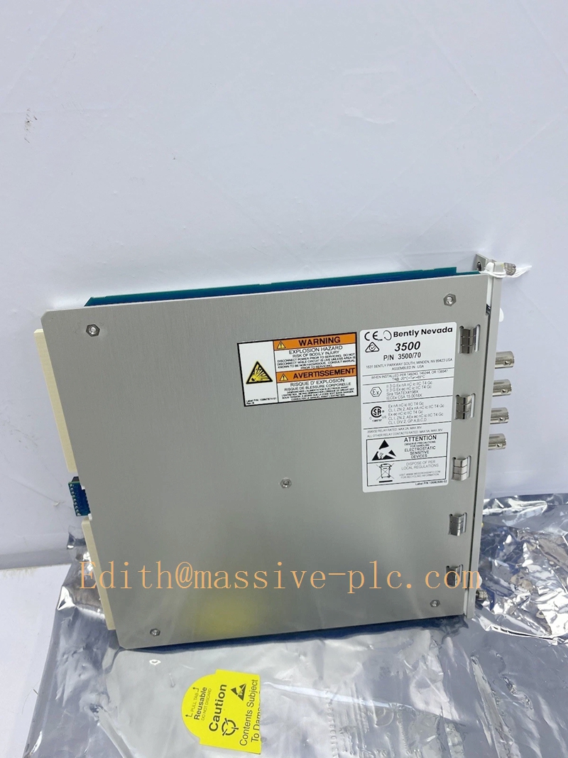
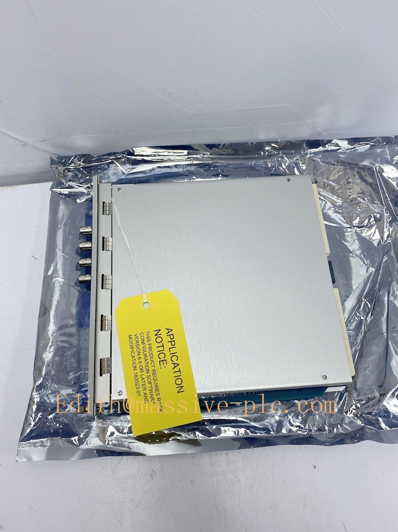
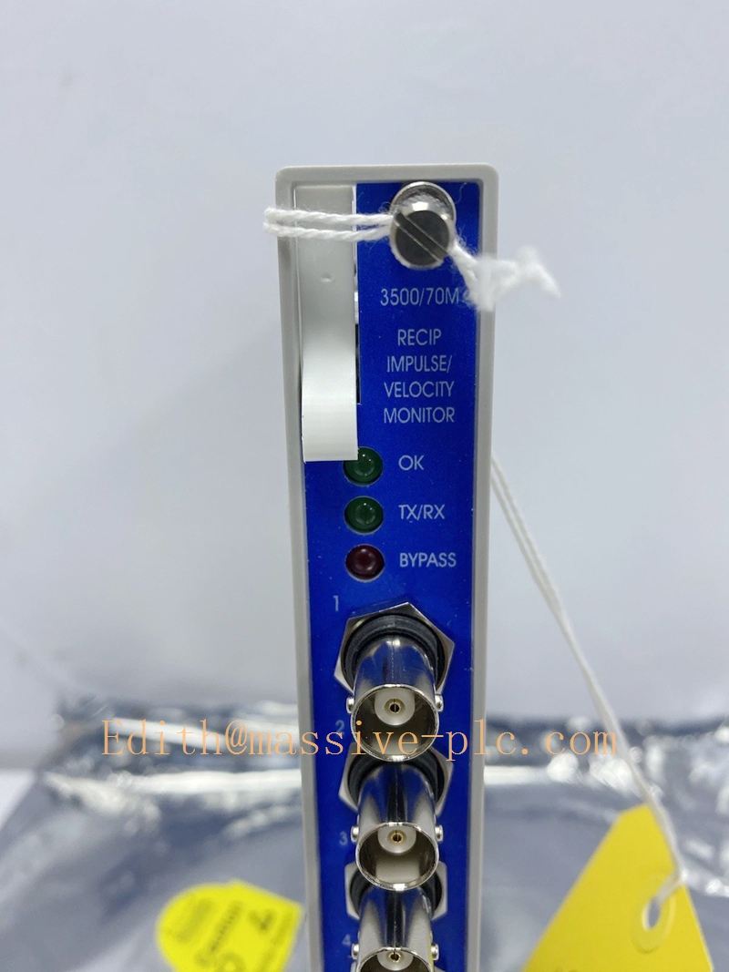
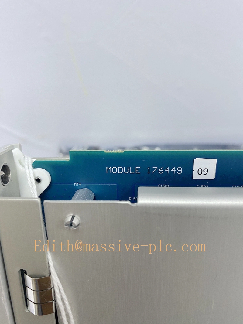
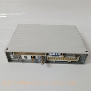
Bently Nevada 3500/70M (176449‑09) Recip Impulse Velocity Monitor
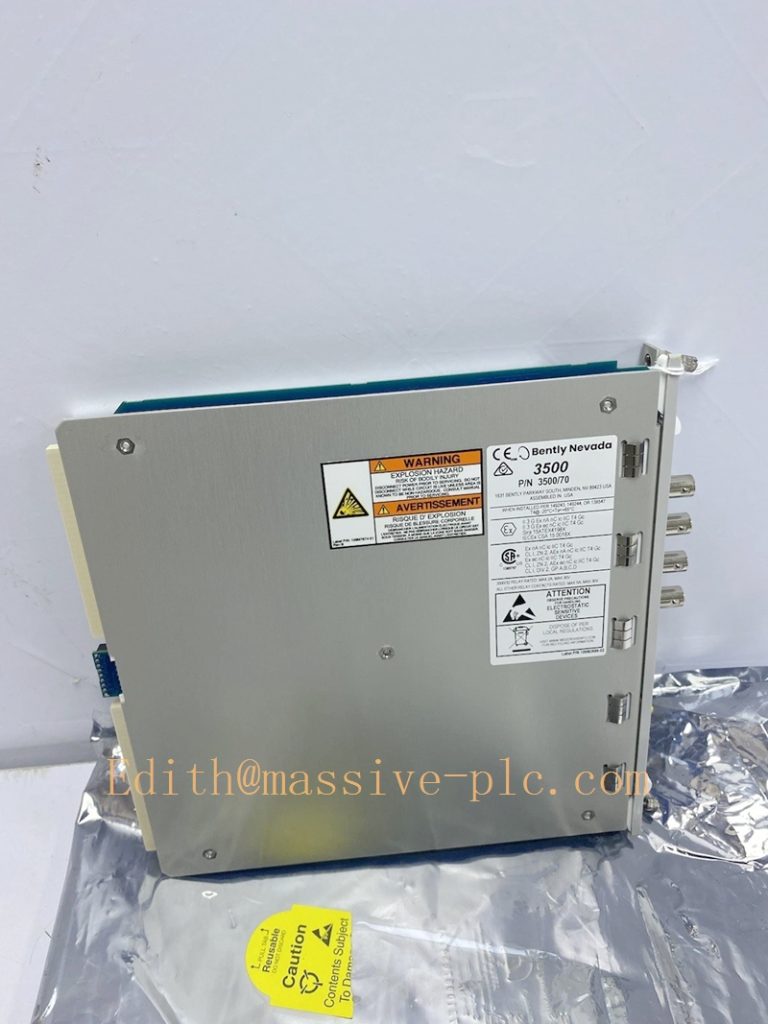
176449-09
Product Overview
176449‑09 is the main monitor board part number for the 3500/70M Recip Impulse Velocity Monitor, a single‑slot dedicated monitoring module within Bently Nevada 3500 machinery‑protection system, specially developed for reciprocating compressors. It accepts input signals from accelerometers and proximity probes, performs impulse acceleration, reciprocating velocity and cross‑head impact measurement, executes real‑time signal conditioning, alarm comparison and sensor fault diagnosis. It detects mechanical looseness, cross‑head wear, valve failure and frame abnormal vibration for reciprocating equipment, delivers protection and predictive‑maintenance data, and complies with API 618 and API 670 standards. This main board must work with matching I/O termination assembly and cannot run independently.
Technical Specifications
| Item | Parameter |
|---|---|
| Part Number | 176449‑09 (3500/70M Main Monitor Board) |
| Number of Channels | 4 independent input channels |
| Measurement Modes | Impulse Acceleration, Acceleration‑2, Reciprocating Velocity, Low‑Frequency Reciprocating Velocity (configurable per channel pair) |
| Sensor Input | Accelerometer, proximity probe (proximitor) signal input |
| Frequency Response | 2 Hz ~ 10 kHz, optimized for reciprocating‑machine impact and vibration capture |
| Power Consumption | 7.7 W typical, powered by rack backplane bus |
| Operating Temperature | ‑30 ℃ ~ +65 ℃ (rack environment); Storage:‑40 ℃ ~ +85 ℃ |
| Form Factor | Single‑slot plug‑in for 3500 instrument rack |
| Weight | Approx. 1.04 kg |
| Front‑panel Indicators | OK, Bypass, TX/RX LED status indicators |
| Configuration | 3500 Rack Configuration Software; configurable Alert / Danger alarm thresholds, filter parameters, measurement mode |
| Compliance | API 618, API 670; SIL‑capable within qualified 3500 system |
| Termination Options | Matches internal‑barrier I/O 135489‑03 or external‑termination I/O assembly |
Key Features
- Four‑channel dedicated reciprocating‑compressor measurement: Multiple selectable measurement modes per channel pair, captures cross‑head impact, frame vibration and mechanical impulse features unique to reciprocating equipment.
- Early mechanical‑fault detection: Identifies cross‑head wear, bolt looseness, valve malfunction, packing failure and frame abnormal vibration before severe equipment damage occurs.
- Complete sensor loop supervision: Continuously monitors transducer and cable status; reports open‑circuit, short‑circuit and sensor fault diagnostics over rack backplane bus.
- Two‑level alarm logic: Independent Alert and Danger alarm setpoints for each channel, supports machinery protection trip interlock logic.
- Seamless 3500 rack integration: Interoperates with relay modules, communication gateways and other reciprocating‑dedicated monitors (3500/72M, 3500/77M) via backplane bus; supports hot‑swap replacement following official maintenance procedure.
- Hazardous‑area support option: Matches I/O assembly with built‑in intrinsic‑safety barriers for field sensors installed in explosive classified zones.
- Predictive‑maintenance data output: Sends vibration waveform and trending data to System 1 software, DCS or SCADA for equipment health analysis.
Typical Applications & Application Scenarios
Main Applications
- Cross‑head impact and acceleration monitoring of reciprocating compressors.
- Reciprocating compressor crankcase / frame velocity vibration measurement.
- Detect cross‑head pin wear, connecting‑rod looseness, valve failure and packing abnormal conditions.
- Provide alarm and trip signal inputs for reciprocating‑machinery protection, supply vibration data for spectrum analysis and condition‑based maintenance.
Industry Scenarios
- Oil & gas: natural‑gas pipeline compressor stations, refinery reciprocating compressors, offshore platform reciprocating units.
- Petrochemical plants: hydrogen compressors, hyper‑compressors and process‑gas reciprocating compressors compressing hydrocarbon media.
- Sites executing API 618 reciprocating‑compressor specification, requiring online mechanical impact and vibration monitoring.
Supporting / Matching Components
- Mandatory paired I/O termination assembly
- 135489‑03: Internal‑termination I/O with integrated intrinsic‑safety barrier (most common for hazardous‑area field sensors)
- External‑termination I/O variant for cabinet pre‑wiring and high‑EMI environments
- Host rack: 3500/05 instrument rack
- Rack power supply: 3500/15 series power‑supply modules
- Field sensors: Accelerometers and proximity probes for reciprocating‑compressor measurement, matched shielded sensor cables
- Auxiliary modules:
- 3500/32M / 3500/33 relay modules: hardware alarm & trip contact output
- 3500/92 / 3500/77M gateway modules: upload monitoring data and alarms to DCS, SCADA, System 1
- Configuration software: Bently Nevada 3500 Rack Configuration Software
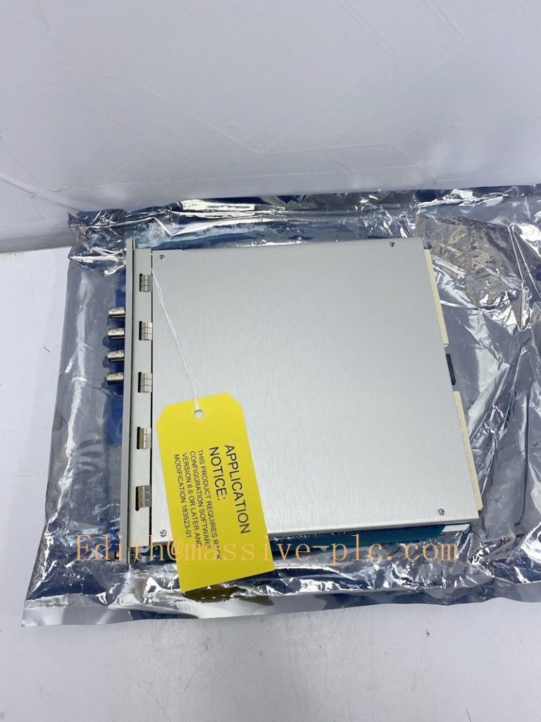
176449-09
Related & Reference Part Numbers
- 135489‑03: Internal IS‑barrier I/O assembly for 3500/70M (must pair with 176449‑09)
- 3500/72M: Recip Rod Position / Rod Drop Monitor (reciprocating‑compressor companion monitor)
- 3500/77M: Recip Cylinder Pressure Monitor (P‑V curve diagnosis for reciprocating compressors)
- 3500/70M‑01‑00: Complete assembly (176449‑09 + 135489‑03 internal barrier I/O)
Note: 3500/70M is exclusively designed for reciprocating compressors, not for general rotating‑machinery vibration monitoring. It is usually deployed together with 3500/72M and 3500/77M to form a full reciprocating‑compressor monitoring solution.
Installation & Maintenance Notes
- 176449‑09 main monitor board must install together with matching I/O termination assembly inside the identical rack slot, standalone operation is prohibited.
- For hazardous‑area applications, only use IS‑certified field sensors and cables with barrier‑type I/O assembly, comply with local hazardous‑area installation standards.
- Use shielded sensor cables; separate signal wiring from high‑power cables to reduce impulse‑signal distortion.
- After hardware installation, verify channel status, sensor fault‑detection and alarm logic inside 3500 configuration software.
- Execute hot‑swap replacement strictly per Bently Nevada official service manual.


 Start Chat




