
Description
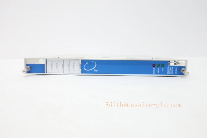
Bently‑Nevada 3500/62 Process Variable Monitor Assembly (163179‑03 + 136294‑01)
Product Description
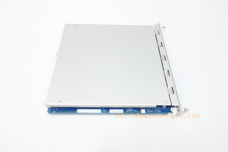
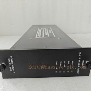
The 3500/62 (163179‑03 + 136294‑01) is a six‑channel Process Variable Monitor module belonging to Bently‑Nevada 3500 machinery protection rack system. The assembly consists of front main processing board 163179‑03 and rear internal screw‑terminal I/O board 136294‑01.
This monitor acquires standard analog process signals including 4‑20 mA current and ‑10 VDC ~ +10 VDC voltage inputs from field transmitters. It converts raw signals into engineering values, compares measurements against user‑configured Alert / Danger setpoints, generates alarm status for machinery protection. It communicates with rack TDI over backplane bus, uploading real‑time process data, alarm events and diagnostic information to System 1 software and 3500 rack configuration tool.
The module supports simplex and TMR triple‑modular‑redundant deployment for safety‑critical applications. Local protection judgment runs on‑board; protection logic remains functional even if TDI network communication fails. OEM production discontinued; supplied only as aftermarket replacement spare for legacy turbomachinery TSI racksBaker Hugh…。
Order‑related PN breakdown‑ Front monitor board:163179‑03‑ Rear internal termination I/O board:136294‑01‑ No third‑party safety agency certification
350062 190085-03M
Technical Specifications
| Item | Specification |
|---|---|
| Complete Assembly PN | 3500/62 (163179‑03 + 136294‑01) |
| Front Main Processing Board | 163179‑03, 6‑channel process variable CPU board |
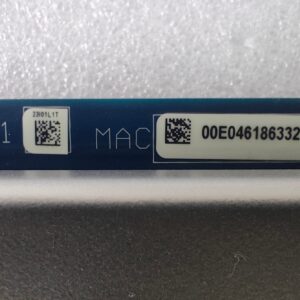
| Rear I/O Daughter‑Board | 136294‑01, internal screw‑terminal termination board |
| Form Factor | Full‑height monitor module, occupies one full‑height rack slot |
| Channel Quantity | 6 independent configurable analog input channels |
| Input Signal Types | 4‑20 mA current input, ‑10 VDC ~ +10 VDC voltage input |
| Measured Parameters | Pressure, flow rate, temperature, liquid level and other process variables |
| Alarm Setting | Independent Alert / Danger setpoint & alarm delay per channel |
| Operation Mode | Simplex mode; TMR triple modular redundant mode (group of three modules) |
| Front‑panel Indicator | Module OK LED, Bypass LED, TX/RX communication LED, channel alarm status indicators |
| Typical Power Consumption | 8.2 W, powered by rack backplane bus |
| Hot‑swap Rule | Rear I/O board supports hot‑swap under rack powered‑on; front main‑board requires slot power‑off |
| Operating Temperature | ‑30 °C ~ +65 °C (‑22 °F ~ +149 °F) |
| Storage Temperature | ‑40 °C ~ +85 °C (‑40 °F ~ +185 °F) |
| Relative Humidity | 5‑95 % RH, non‑condensing |
| Dimension(H×W×D) | 241.3 mm ×24.4 mm ×241.8 mm (9.50 in ×0.96 in ×9.52 in) |
| Product Status | Discontinued OEM production, aftermarket spare‑part only |
Variant note‑ Different rear I/O options: general voltage/current board, intrinsic‑safe barrier I/O board, external termination board. This unit uses internal screw‑terminal 136294‑01.
Key Features & Benefits
- Multi‑signal analog acquisition: Accepts industry‑standard 4‑20 mA and ±10 VDC transmitter signals, integrates pressure, flow, level and temperature process variables into 3500 machinery‑protection platform, realizes correlation analysis between process condition and machine mechanical status.
- Flexible simplex / TMR redundant architecture: Supports simplex conventional monitoring; for safety‑instrumented system, three 3500/62 modules can be grouped for TMR 2‑out‑of‑3 voting, meeting high‑reliability protection requirements.
- Independent on‑board protection logic: Alarm comparison and protection judgment are executed locally inside module hardware. Loss of TDI network communication will not disable alarm and interlock functions, ensuring machinery‑protection integrity.
- Comprehensive self‑diagnosis capability: Detects transmitter open‑circuit, short‑circuit, module hardware fault; fault codes and time‑stamped events are stored into rack event‑log for fast troubleshooting.
- System‑wide logic linkage: Channel alarm status can be mapped to 3500/33 relay‑output module, driving hard‑wire dry‑contact signals for local annunciator, DCS interlock and emergency trip circuit.
- Backward‑compatible maintainable architecture: Fully compatible with 3500 rack ecosystem, works cooperatively with 3500/15 redundant power supply, 3500/22‑TDI, 3500/33 relay module. Internal screw‑terminal rear board simplifies field wiring maintenance; rear I/O supports online hot‑swap.
Application Fields
‑ Power‑generation, petrochemical and natural‑gas facilities: monitors critical process parameters of steam turbines, gas turbines, centrifugal compressors, reciprocating compressors; integrates pressure, flow, temperature and level signals into 3500 TSI protection system complying with API‑670 standard.‑ Safety‑critical rotating‑machinery sites requiring simplex or TMR redundant process‑variable protection.‑ Spare‑part replacement and retrofit for legacy 3500 racks originally equipped with 3500/62 (163179‑03+136294‑01) internal‑termination process‑variable‑monitor assembly.
Related Recommended Products
‑ 3500/05 series: 3500‑system rack chassis‑ 3500/15 series: Redundant rack power‑supply modules‑ 3500/22 / 3500/22M TDI: Transient‑data‑interface gateway for configuration download, event‑log storage and System 1 data transmission‑ 3500/33‑01‑00: Multi‑channel relay‑output module, converts process‑variable alarm status to hard‑wire dry‑contact signals‑ 3500 Rack Configuration Software: Tool for channel engineering‑unit scaling, alert/danger setpoint configuration, TMR‑mode parameter setup‑ System 1® Condition‑Monitoring Software: Host platform for process‑variable trending, alarm history review and root‑cause analysis.
Installation and Maintenance
Installation
- Assemble front processing board 163179‑03 and matched rear‑I/O board 136294‑01 as a complete unit; insert assembly into any available full‑height slot of 3500 rack. For TMR application, install three 3500/62 modules in adjacent slots.
- Wire field 4‑20 mA / voltage transmitter cables onto rear‑board screw terminals, strictly follow instrument wiring specifications.
- Connect laptop to TDI via USB port, launch 3500 Rack Configuration Software; set channel input type, scale engineering range, configure Alert / Danger setpoints and delay parameters; download configuration to rack.
- Power‑up rack; verify front‑panel module OK‑LED stays illuminated; inspect rack event‑log for input signal faults or module hardware alarms; simulate analog signal to validate alarm triggering and relay‑output linkage.
Important Note: Only rear‑side I/O board supports hot‑swap under rack powered‑on. Front 163179‑03 main‑board must be replaced with corresponding slot power disabled. Improper channel scaling or setpoint configuration may cause false‑alarm or missing‑protection risk.
Maintenance
- Periodically inspect rear‑board screw terminals for dust accumulation, corrosion and loose wiring connections during site routine inspection.
- Regularly download rack event‑log to review transmitter faults, channel abnormal status and alarm historical records.
- When rear‑I/O circuit fault occurs, perform hot‑swap for rear termination board under rack powered‑on condition, verify each‑channel measurement function after replacement.
- When front‑processing‑board hardware fault occurs, cut off slot power before replacing 163179‑03 board; reassemble with matched rear I/O module, re‑download rack configuration and validate full‑function recovery.
- Avoid mechanical shock and conductive contamination during module‑handling. Refer to Bently‑Nevada official document Doc‑141541 (3500/62 Process Variable Monitor Datasheet & Operation Manual) for complete installation constraints and detailed troubleshooting guidanceBaker Hugh。

 Start Chat




