
Description
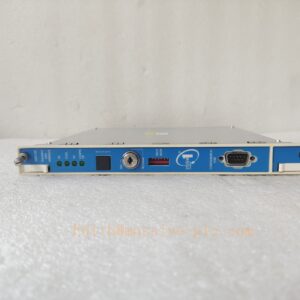
Bently‑Nevada 3500/46‑03‑00 Hydro Monitor Assembly
Product Description
The 3500/46‑03‑00 is a dedicated four‑channel hydro‑turbine monitor module within Bently‑Nevada 3500‑series machinery protection rack. It consists of front hydro‑monitor processing board and rear I/O termination board. This module is purpose‑built for hydro‑generator units, accepting signals from proximity probes, seismic transducers, air‑gap sensors and dynamic‑pressure sensorsMoore Auto….
It executes multi‑parameter measurement, alarm comparison and machinery protection logic for hydroelectric assets. It supports multimode alarm groups, which can switch alarm thresholds automatically according to machine operating conditions such as load zone, startup‑shutdown state. The module communicates with rack TDI/TDIM via backplane bus, uploading real‑time measurements, alarm status and waveform data to System 1 condition‑monitoring software.
Order code breakdown:3500/46‑03‑00‑03:Rear I/O = Internal screw‑terminal termination board for hydro‑monitor multi‑sensor inputs‑00:No third‑party safety agency certificationOEM production discontinued; only supplied as aftermarket replacement spare for legacy hydro‑plant TSI protection racks.
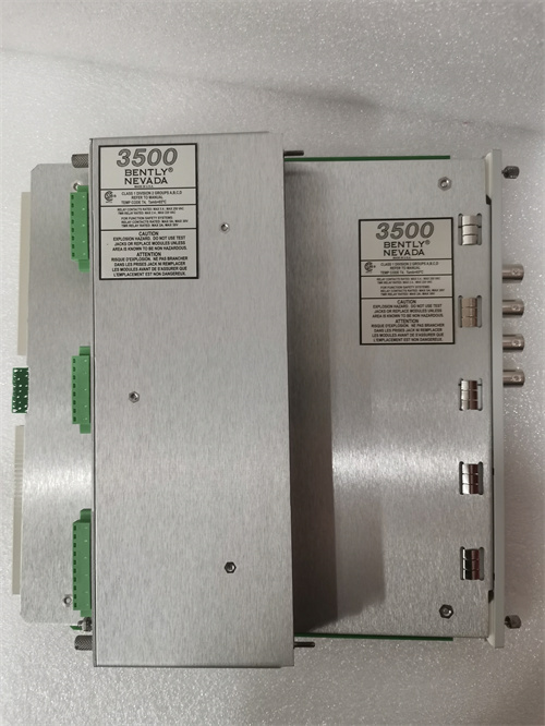
350046M 169459‑02
Technical Specifications
| Item | Specification |
|---|---|
| Complete Assembly PN | 3500/46‑03‑00 (Front processing board + rear internal‑termination I/O board) |
| Form Factor | Full‑height monitor module, occupies one full‑height rack slot |
| Channel Quantity | 4 independent configurable input channels, configured in channel‑pair groupsBaker Hugh… |
| Supported Sensor Types | Proximity probe, seismic velocity / acceleration transducer, air‑gap sensor, dynamic pressure sensorMoore Auto… |
| Measurement Functions | Hydro Radial Vibration, Hydro Air Gap, Hydro Velocity, Hydro Acceleration, Hydro Thrust, Hydro Dynamic Pressure, Stator End Winding (SEW) vibrationBaker Hugh… |
| Multimode Function | Up to 8 sets of alert / danger alarm parameters per channel; mode switch via discrete contact input or software commandMoore Auto… |
| Alarm Logic | User‑configurable Alert (warning) and Danger (trip) setpoints; independent alarm delay per channel |
| Output Interface | Recorder analog output; backplane digital data to TDI module; discrete multimode control input |
| Front‑panel Indicator | Module OK LED, Channel alarm LED status indicators |
| Hot‑swap Rule | Rear I/O board supports hot‑swap under powered‑on rack; front processing board requires slot power‑off before removal |
| Typical Power Consumption | ~11.0 W, powered by rack backplane bus |
| Operating Temperature | ‑30 °C ~ +65 °C (‑22 °F ~ +149 °F) |
| Storage Temperature | ‑40 °C ~ +85 °C (‑40 °F ~ +185 °F) |
| Relative Humidity | 5‑95 % RH, non‑condensing |
| Dimension(H×W×D) | 241.3 mm ×24.4 mm ×241.8 mm (9.50 in ×0.96 in ×9.52 in) |
| Product Status | Discontinued OEM production, aftermarket spare‑part only |
Variant note‑01:External termination rear I/O board‑02:ET‑style external connector rear I/O board‑03:Internal screw‑terminal rear I/O board (this model)
Key Features & Benefits
- Hydro‑turbine‑oriented multi‑sensor compatibility: One module supports proximity, seismic, air‑gap and dynamic‑pressure sensors, covers most measurement parameters for hydro‑generator units, reduces rack‑slot consumptionBaker Hugh….
- Powerful multimode alarm mechanism: Each channel stores up to eight groups of alarm threshold parameters. Alarm setpoints can be auto‑switched responding to machine operating modes (rough‑load zone, startup, normal‑load, shutdown), avoids false alarms under transient hydro‑unit operating conditionsMoore Auto….
- Comprehensive hydro‑specific measurement items: Supports radial shaft vibration, air‑gap between rotor‑stator, thrust position, casing vibration, stator‑end‑winding vibration and dynamic pressure monitoring, fulfills complete hydro‑unit protection requirementsBaker Hugh….
- Independent protection logic: Monitor protection voting runs locally on module hardware. Protection and alarm functions keep working even if TDI communication fails; network loss will not block machinery trip outputs.
- Analog recorder output: Each channel provides analog output for local chart recorder or third‑party acquisition device. Recorder‑output short‑circuit will not damage module hardware.
- Backward‑compatible maintainable architecture: Fully compatible with 3500‑series rack system, cooperates with 3500/22‑TDI, 3500/33‑relay, 3500/15‑redundant power supply. Rear‑side internal‑screw‑terminal board facilitates field wiring maintenance.
Application Fields
‑ Hydroelectric power plants: continuous online protection & condition monitoring for vertical / horizontal hydro‑turbine‑generator sets; monitors rotor‑stator air‑gap, radial vibration, thrust position, casing seismic vibration, stator‑end‑winding vibration and dynamic pressure parametersBaker Hugh….‑ Hydropower assets requiring multi‑mode adaptive alarm logic for varying load‑zone operating conditions.‑ Spare‑part replacement and retrofit for legacy 3500 hydro‑monitor racks originally equipped with 3500/46‑03‑00 internal‑termination hydro‑monitor assembly.
Related Recommended Products
‑ 3500/05 series: 3500‑system rack chassis‑ 3500/15 series: Redundant rack power‑supply modules‑ 3500/22 / 3500/22M TDI: Rack transient‑data‑interface gateway for configuration download, event‑log storage and System 1 data transmission‑ 3500/33‑01‑00: Multi‑channel relay‑output module, converts monitor alarm status to hard‑wire dry‑contact signals for trip & annunciator system‑ 3500 Rack Configuration Software: Tool for channel‑function selection, multimode‑alarm‑parameter setup and rack configuration download‑ System 1® Condition‑Monitoring Software: Host diagnostic platform receiving hydro‑unit measurement and waveform data.
Installation and Maintenance
Installation
- Assemble front hydro‑monitor processing board and matched rear‑03 internal‑screw‑terminal I/O board as one complete unit; insert assembly into any available full‑height slot of 3500 rack.
- Wire field sensor cables and multimode discrete‑control signal onto rear‑board screw terminals, strictly comply with sensor wiring specification.
- Connect laptop to TDI module via USB port, launch 3500 Rack Configuration Software; select channel measurement type, configure alert / danger setpoints and multimode‑group parameters, download configuration to rack.
- Power‑up rack; verify front‑panel module OK‑LED keeps illuminated; check rack event‑log for monitor‑hardware or signal‑input faults; simulate sensor signals to validate alarm‑trigger and relay‑output action.
Important Note: Only rear‑side I/O board supports hot‑swap when rack remains powered‑on. Front processing board must be removed after corresponding slot power disabled. Improper multimode‑parameter configuration may cause false‑alarm or missing‑protection risk.
Maintenance
- Periodically inspect rear‑board screw terminals for dust accumulation, corrosion and loose wiring connections during site routine inspection.
- Regularly download rack event‑log to review channel signal faults, sensor abnormal status and alarm records.
- When rear‑I/O circuit fault occurs, perform hot‑swap for rear termination board under rack powered‑on condition, verify channel measurement function after replacement.
- When front‑processing‑board hardware fault occurs, cut off slot power before replacing front board; reassemble with matched rear I/O module, re‑download rack configuration and validate full‑function recovery.
- Avoid mechanical shock and conductive contamination during module‑handling. Refer to Bently‑Nevada official document Doc‑144408 (3500/46 Hydro Monitor Datasheet & Operation Manual) for complete installation constraints and detailed troubleshooting guidance.

 Start Chat




