
Description
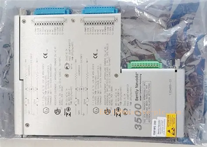
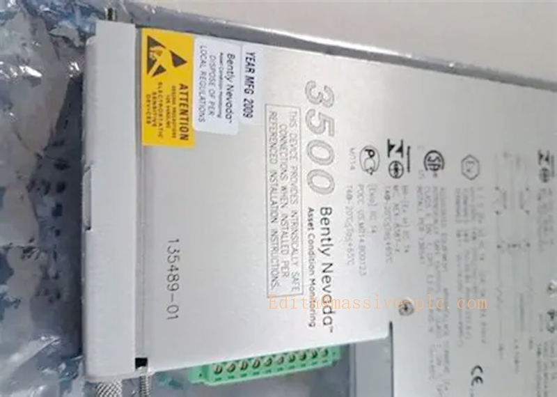
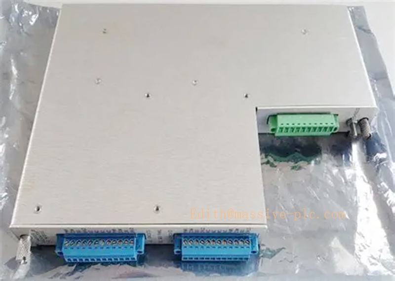
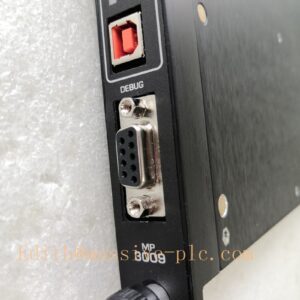
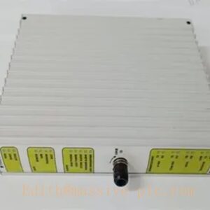
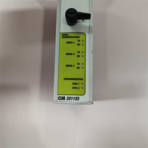
Bently Nevada 3500/42M (135489‑02) Intrinsically Safe I/O Assembly
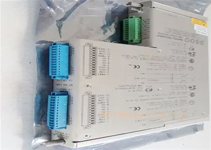
3500/42M 135489-01
Product Overview
135489‑02 is the rear‑mount intrinsic‑safety I/O assembly for the Bently Nevada 3500/42M Proximitor / Seismic monitor module, designed for hazardous area field sensor wiring. This unit integrates built‑in IS safety barriers and internal screw‑type termination terminals. Channel hardware is hardware‑fixed: Channels 1‑2 support proximity probes or accelerometers; Channels 3‑4 are dedicated for Velomitor velocity sensors. It cannot work independently and must be mechanically and electrically mated with a 3500/42M monitor mainboard to implement complete vibration and position measurement functions. It meets API‑670 and SIL‑2 system requirements, widely used in oil & gas, petrochemical, power generation and heavy‑duty rotating‑machinery protection systems.
Typical Applications ‑ Mixed‑sensor protection for turbines and centrifugal compressors: shaft displacement via eddy‑current probes plus casing velocity vibration via Velomitor sensors ‑ Rotating machinery monitoring for Class I / Div hazardous classified field zones ‑ Radial vibration, thrust position, casing absolute vibration monitoring for steam & gas turbines ‑ Generator and large critical pump condition monitoring and protection ‑ Deliver processed measurement data to DCS, PLC or monitoring host over the 3500 rack backplane bus
Technical Specifications
| Item | Specification |
|---|---|
| Part Number | 135489‑02 (I/O Assembly for 3500/42M) |
| Termination Style | Internal screw termination, integrated intrinsic safety barriers |
| Hardware Channel Allocation | Ch1‑2: Proximitor / Accelerometer; Ch3‑4: Velomitor velocity sensor only |
| Mating Mainboard | 3500/42M series monitor mainboard |
| Supported Transducers | 3300XL series proximity probes, accelerometers, Velomitor velocity transducers |
| Power Source | Supplied by mated 3500/42M monitor via rack 24 VDC backplane |
| Installation | Rack rear side installation, mate with front‑plug 3500/42M mainboard |
| Operating Temperature | ‑40 °C ~ +85 °C |
| Certifications | SIL‑2 capable, API‑670 compliant, CE, hazardous‑area intrinsic‑safety approvals |
| Approximate Weight | 0.46 kg |
| Recorder Output | Buffered recorder output per channel for portable field test instruments |
Important Note: 135489‑02 is purely an I/O rear assembly. It contains no measurement processing logic. System operation requires a matching 3500/42M main monitor board.
Core Features
- Fixed mixed‑sensor channel hardware: two channels for proximity / acceleration signals, two dedicated Velomitor channels, optimizes cabinet slot usage for mixed‑sensor field sites.
- On‑board intrinsic safety barriers: removes requirement for external barrier devices, provides over‑voltage and over‑current protection for field sensors located in hazardous zones.
- Internal termination design: field cables terminate directly onto rear‑assembly screw terminals without extra external terminal blocks.
- Mechanical‑electrical interlocking structure: must lock firmly with 3500/42M mainboard; mismatched I/O assembly leads to measurement error or communication failure.
- Per‑channel buffered recorder outputs for on‑site troubleshooting and signal verification.
- Rich built‑in diagnostics: open‑circuit, short‑circuit and IS barrier fault detection; all fault events are time‑stamped and logged in the 3500 system.
- High‑immunity industrial hardware, resistant to EMI interference for heavy‑noise plant environments.
- Suitable for SIL‑2 safety‑related machinery protection loops.
Adaptive Quality Assurance and Test Protocol (AQAT)
The AQAT procedure covers factory acceptance test and site acceptance test for 135489‑02, verifying mechanical mating, barrier performance, signal path integrity and channel‑specific sensor compatibility.
4.1 Factory QA Test
‑ Mechanical fit test: mate with qualified 3500/42M mainboard to verify locking and back‑contact reliability. ‑ Power‑on self‑test: validate barrier health status, internal circuit self‑check and system bus communication. ‑ Channel signal injection test: apply simulated proximity / acceleration signals to Ch1‑2 and Velomitor velocity signals to Ch3‑4; verify gain, linearity and frequency response versus datasheet tolerances. ‑ Intrinsic‑safety barrier characteristic test: confirm voltage‑current limiting performance meets hazardous‑area specification. ‑ Field fault simulation: simulate open‑circuit and short‑circuit conditions to validate sensor‑fault alarm reporting. ‑ Powered temperature‑cycle burn‑in screening to screen early‑life component defects. ‑ Issue formal factory test report before product shipment.
4.2 On‑Site QA Procedure
‑ Installation Qualification (IQ): confirm secure mechanical locking between 135489‑02 and 3500/42M mainboard; check terminal torque, grounding, cable separation and hazardous‑area wiring compliance. ‑ Operational Qualification (OQ): inject test signals for each channel group; cross‑check measured values, alarm trigger action and host‑system data consistency. ‑ Performance Qualification (PQ): long‑term observation under real process conditions; cross‑reference readings with portable vibration analyser. ‑ Adaptive retest: perform full channel verification after I/O assembly replacement, sensor swap or configuration modification. Preserve all test records for audit traceability.
All test documentation shall be archived for asset management and audit purposes.
Field Engineer Technical Instructions
5.1 Installation Instructions
‑ Mount 135489‑02 at the rear of the 3500 rack, fully lock together with front‑side 3500/42M monitor mainboard. Confirm latches are fully engaged. ‑ Follow fixed hardware channel definition strictly: connect proximity probes / accelerometers to Channel 1‑2; connect Velomitor sensors only to Channel 3‑4. Mis‑wiring will produce measurement deviation or hardware damage. ‑ For hazardous‑area deployment, strictly comply with IS barrier parameters and local hazardous‑area installation codes. ‑ Separate analog sensor cables from high‑power high‑voltage cables; observe maximum allowable transducer cable length limits. ‑ Implement plant‑standard grounding: isolate analog signal grounding from heavy‑power grounding to reduce noise coupling.
5.2 Commissioning Steps
‑ Complete mechanical assembly of 3500/42M mainboard plus 135489‑02 I/O assembly. ‑ Open 3500 Rack Configuration Software. Configure channel‑pair functions according to actual sensor types, set transducer sensitivity, measurement range, Alert and Danger alarm thresholds. ‑ Download configuration parameters to monitor module and reset module to activate settings. ‑ Execute gap‑voltage check for proximity probe channels; validate raw signal readings before enabling protection alarms. ‑ Force‑test each channel to verify relay output action and DCS / HMI indication consistency.
5.3 Common Field Troubleshooting
‑ Barrier / Sensor Fault Alarm: Inspect field cable open‑circuit / short‑circuit, loose terminals; double‑check sensor‑to‑channel wiring mapping. ‑ Abnormal Readings: Confirm correct sensor‑channel matching; check grounding and EMI noise; verify software sensitivity matches physical transducer specifications. ‑ Communication Loss: Check mechanical locking status between I/O assembly and mainboard, rack backplane condition and system controller status.
Warning: Bypass protection alarms only during short‑period maintenance work. Restore full protection functions before rotating equipment returns to normal operation.
5.4 Maintenance Notes
‑ Monitor front‑panel LED indicators during routine site inspections. ‑ No user‑serviceable parts inside I/O assembly; do not disassemble the housing. ‑ Keep complete configuration backup file for rapid hardware replacement upon failure.
Related Series Models
| Model | Description |
|---|---|
| 135489‑02 | 3500/42M IS I/O Assembly, internal termination, 2×Prox/Accel + 2×Velomitor |
| 135489‑01 | 3500/42M IS I/O Assembly, 4‑channel Proximitor / Accelerometer only |
| 135489‑03 | 3500/42M IS I/O Assembly, 4‑channel Velomitor only |
| 126632‑01 | 3500/42M non‑IS external‑termination I/O assembly |
| 140734‑02 | 3500/42M monitor main processing board (no field terminals) |
| 3500/44M | 4‑channel differential expansion & speed monitor |
| 3500/45M | Auxiliary position monitor module |
| 3500/50 | Keyphasor module for phase reference and rotational speed acquisition |


 Start Chat




