
Description
Meta Description
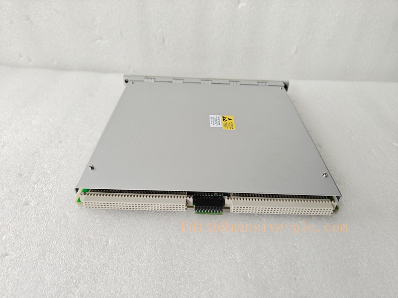
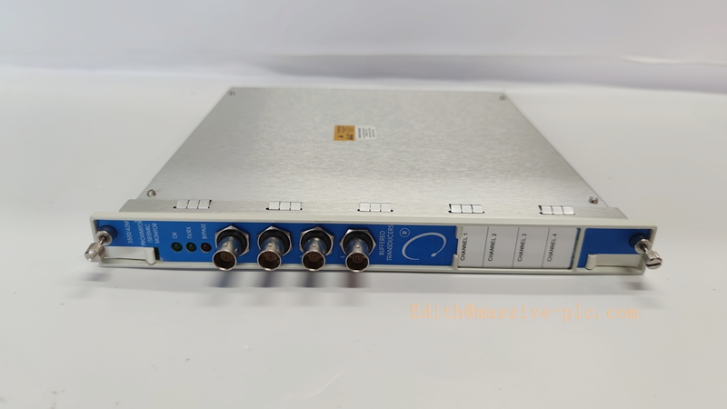
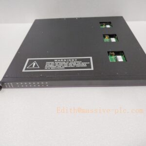
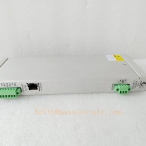
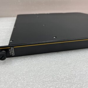
Bently Nevada 3500/42-09-00 (176449-02 + 140471-01) is a 4-channel proximity/seismic monitor for critical rotating machinery, supporting vibration, displacement, acceleration and velocity measurements, fully compliant with API 670 standards for industrial safety monitoring.
Core Product Introduction
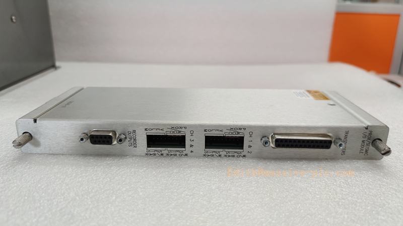
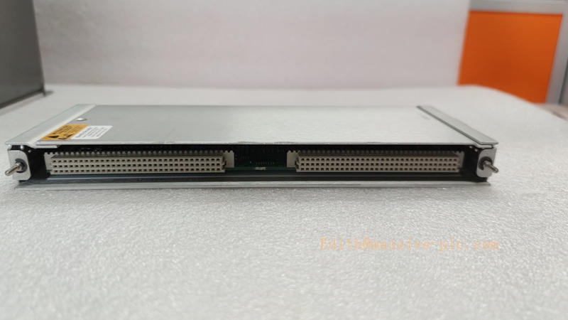
- Product Identity: A 4-channel intelligent vibration and position monitoring module belonging to the Bently Nevada 3500 TSI system, assembled with main part 176449-02 and internal terminal I/O sub-module 140471-01.
- Core Function: Accepts signals from eddy-current proximity sensors, velocity pickups and accelerometers, processes real-time machinery health data, and compares readings with user-programmable alarm thresholds.
- Typical Application: Designed for continuous condition monitoring on steam turbines, compressors, pumps, generators and other large rotating assets in power, oil & gas and process industries.
- Key Advantage: Channels can be configured in paired groups to run two independent measurement tasks simultaneously, delivering higher flexibility than standard 3500/40M monitors.
Main Technical Specifications
- Channel Count: 4 fully independent configurable monitoring channels
- Supported Transducers: Proximity probes, velocity sensors, accelerometers
- Typical Power Consumption: 7.7 W
- Input Impedance: 10 kΩ for proximity and acceleration inputs
- Transducer Supply Voltage: -24 V DC
- Recorder Output: 4–20 mA analog signal
- Measurement Accuracy: ±0.33% of full scale typical, maximum ±1% excluding filter effects
- Weight: 910 g
- Warranty: 12 months for new original units
Quality Control Procedure
- Incoming Inspection: Verify part serial numbers, physical integrity and original factory labeling against Bently Nevada official part database.
- Functional Bench Test: Power on the module, simulate all 4 channel inputs, confirm LED status indicators and alarm relay logic operate correctly.
- Accuracy Calibration: Inject standard reference signals to validate full-scale measurement error stays within the published ±1% maximum tolerance.
- Burn-in Test: Run continuous 72-hour powered operation under normal industrial temperature range to eliminate early failure risks.
- Final Documentation: Generate full test report, attach calibration sticker and release the unit with formal quality certificate.
Related Model Recommendations
- 3500/42M-09-00: Upgraded M-series variant with higher shaft absolute vibration measurement precision, ideal for high-end turbine supervision.
- 138700-01: External terminal shaft absolute vibration I/O module, suitable for field wiring scenarios that require no internal cabinet terminals.
- 135489-01: Internal safety barrier I/O version for 4× displacement/acceleration measurements, certified for hazardous area installation.
- 3500/45: 4-channel dedicated position monitor, optimized for axial displacement, differential expansion and shell expansion measurement tasks.
Frequently Asked Questions
- Q1: Can this module mix different sensor types on separate channels?
- A: Yes, paired channels can be programmed independently to support different measurement types at the same time.
- Q2: Does it comply with API 670 industry standard?
- A: Fully compliant, the whole 3500 monitoring system series is designed and verified to meet API 670 requirements.
- Q3: What is the difference between 3500/42 and 3500/40M?
- A: 3500/42 adds full acceleration, velocity and seismic measurement functions, while 3500/40M only supports basic proximity vibration monitoring.
- Q4: Can I replace an old 3500/42 unit directly with this version?
- A: Most versions are backward compatible, but you must confirm firmware revision and rack slot configuration before hot swap.
Installation and Configuration Guide
- Mechanical Mounting: Insert the module into an empty slot of the 3500 system rack, lock the front panel screws firmly to ensure reliable backplane connection.
- Field Wiring: Connect all sensor cables to the 140471-01 internal terminals strictly following the official wiring diagram, avoid sharp bends and keep signal cables separated from high-voltage power lines.
- Grounding: Complete single-point system grounding at the 3500 rack I/O module location, never create multiple grounding loops that introduce common-mode interference.
- Software Configuration: Launch the 3500 Rack Configuration Software, assign measurement functions for each paired channel, set appropriate alert and danger alarm thresholds for your machinery.
- Final Validation: Perform full channel signal injection test, verify all alarm relays trigger correctly, then save and upload the final configuration to the system rack.

 Start Chat




