
Description
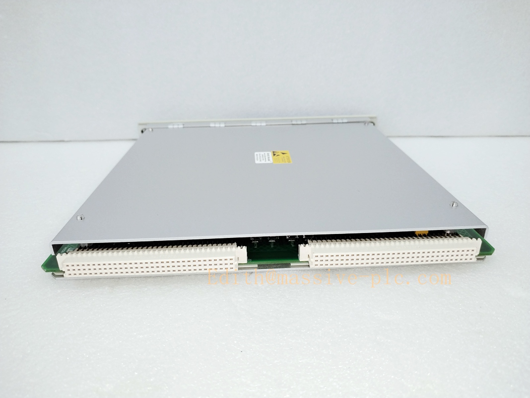
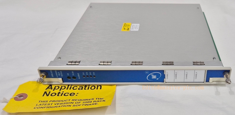
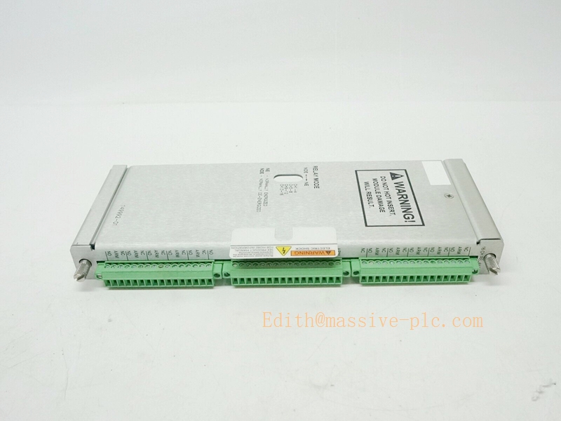
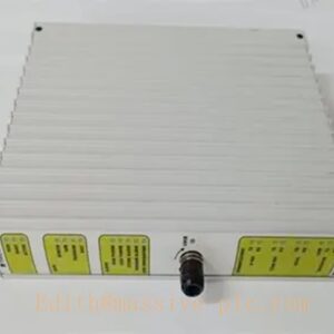
Bently‑Nevada 3500/32‑01‑00 4‑Channel Relay Output Assembly (149986‑02 Main Board + 125720‑01 Rear I/O Module)
Product Description
The 3500/32‑01‑00 (3500/32M) is a full‑height 4‑channel programmable relay output assembly for Bently‑Nevada 3500‑M‑series machinery‑protection rack本特利振动…. The assembly comprises front‑side logic processor main board 149986‑02 and rear‑mount relay contact I/O daughter‑board 125720‑01.
The 149986‑02 main board receives alarm status (Alert, Danger, Not‑OK, PPL) from all monitor channels across the rack via backplane bus, executes user‑configured AND/OR voting alarm‑drive logic, and sends drive commands to rear‑side relay hardware.
The 125720‑01 rear I/O module contains four epoxy‑sealed SPDT relay contacts and built‑in screw‑terminal field‑wiring terminations. It converts logic commands into hard‑wired dry‑contact outputs for DCS interlock, local alarm annunciation and machinery trip circuits. Multiple 3500/32 modules may co‑exist within one rack; they install in any full‑height slot to the right of TDI (3500/22). This assembly cannot work standalone; it depends on rack backplane power and communication from TDI/rack interface module. OEM manufacturing discontinued; supplied only as aftermarket replacement spare for legacy turbomachinery TSI systems.
Technical Specifications
| Item | Specification |
|---|---|
| Complete Assembly PN | 3500/32‑01‑00 |
| Front Main Processor Board | 149986‑02 (3500/32M logic CPU board) |
| Rear Relay I/O Daughter‑Board | 125720‑01 (4‑Ch SPDT relay output with internal screw terminals) |
| Channel Count | 4 independent relay output channels |
| Relay Type | SPDT, epoxy‑sealed, built‑in 250 Vrms arc suppressor |
| Contact Rating | 5 A @24 VDC /120 VAC; mechanical life 100 000 cycles at rated load |
| Relay Mode | Per‑channel configurable: Normally‑energized / Normally‑de‑energized (fail‑safe trip support) |
| Alarm‑Drive Logic | Programmable AND / OR voting; inputs: Alert, Danger, Not‑OK, PPL from any rack monitor channelBaker Hugh… |
| LED Indicators | OK, TX/RX communication, per‑channel CH‑ALARM status LED on front panel |
| Typical Power Consumption | 5.8 WBaker Hugh… |
| Form Factor | Full‑height front main board + full‑height rear plug‑in I/O daughter‑board |
| Operating Temperature | ‑30 °C ~ +65 °C (‑22 °F ~ +149 °F) |
| Storage Temperature | ‑40 °C ~ +85 °C (‑40 °F ~ +185 °F) |
| Relative Humidity | 5‑95 % RH, non‑condensing |
| Dimension(H×W×D) | 241 mm × 24.4 mm × 242 mm (9.50 in × 0.96 in × 9.52 in) |
| Approximate Weight(complete set) | 0.70 kg (1.54 lbs) |
| Product Status | Discontinued OEM production, aftermarket spare‑part only |
Key Features & Benefits
- Flexible rack‑wide voting relay outputs: Each of four relays can be assigned to any combination of monitor‑channel alarm statuses within the same rack; supports complex AND‑OR interlock logic for turbomachinery alarm and trip applications without external logic hardware本特利振动….
- Fail‑safe configurable relay behaviour: Each channel can be set as normally‑energized or normally‑de‑energized, meeting safety‑trip requirements for loss‑of‑power fail‑safe design. Epoxy‑sealed relays with arc‑suppression enhance reliability under industrial switching transients.
- Internal field‑wiring termination: Dry‑contact field‑wiring connects directly onto screw terminals integrated on rear‑side 125720‑01 module, eliminating separate external terminal blocks and reducing cabinet‑wiring complexity.
- Comprehensive diagnostic indication: Front‑panel LEDs show module health, rack‑backplane communication status and individual‑channel alarm activation status; fault events logged to rack event‑log for troubleshooting.
- Multi‑module expandable architecture: Multiple 3500/32‑01‑00 assemblies can be populated inside one 3500‑M‑series rack to increase total relay‑output count for large‑scale TSI projects.
- Drop‑in backward‑compatibility: Compatible with 3500‑M‑series monitors, TDI, power‑supply hardware and legacy rack firmware. Rear‑side 125720‑01 supports hot‑swap replacement; front‑side 149986‑02 main board requires slot power removal for replacement.
Application Fields
- Machinery‑protection racks for steam turbines, gas turbines, centrifugal / axial compressors in power‑generation, petrochemical and oil‑gas facilities, providing hard‑wired dry‑contact alarm and trip‑interlock signals towards DCS, ESD and local annunciator panels.
- Rotating‑equipment TSI systems where multi‑channel alarm‑voting logic is required for shaft‑vibration, thrust‑position, speed and bearing‑temperature protection functions.
- Spare‑part replacement and retrofit for legacy 3500‑M‑series racks deployed with 3500/32‑01‑00 relay assemblies.
Related Recommended Products
- 3500/22‑01‑01‑00 (TDI‑Transient Data Interface): Rack gateway, mandatory for backplane configuration and event‑log handling
- 3500/15 series: Rack power‑supply assemblies
- 3500/40M / 3500/42M / 3500/50 / 3500/60 series: Monitor modules supplying alarm‑status inputs to 3500/32 relay assembly
- 125720‑02: Alternative rear‑I/O variant for SIL‑2 / hazardous‑area functional‑safety qualified systems
- 3500 Rack Configuration Software: Tool for relay‑voting‑logic setup and parameter download
Installation and Maintenance
Installation
- Assemble 149986‑02 front main board firmly mated with 125720‑01 rear relay I/O daughter‑board; insert complete assembly into any full‑height slot located to the right of TDI module.
- Wire DCS / ESD / annunciator field‑cables to SPDT dry‑contact screw terminals on rear‑side 125720‑01, strictly following site interlock‑schematics and safety‑drawings.
- Open 3500 Rack Configuration Software; define voting‑logic conditions for each relay channel (select source monitor‑channels, set AND/OR logic, configure energize‑mode). Download configuration to rack.
- Apply rack power; verify front‑panel OK‑LED is illuminated; inspect rack event‑log for module‑health and communication‑fault diagnostics. Manually simulate alarm conditions to validate relay‑contact switching action.
Important Note: Only rear‑side 125720‑01 I/O supports hot‑swap under rack powered‑on condition. Front‑side 149986‑02 main board must be inserted / removed with corresponding rack‑slot power disabled. Relay voting‑logic is entirely defined via rack configuration software, no hardware‑jumper setting for alarm‑source selection.
Maintenance
- Perform periodic visual inspection: check rear‑module screw terminals, connectors for dust, corrosion and loose wiring connections.
- Regularly review rack‑event‑log for relay‑module fault or backplane‑communication‑fault alarms.
- For rear‑I/O relay‑contact fault: hot‑swap 125720‑01 while rack remains powered‑on; verify relay‑switching function after replacement.
- For main‑board logic fault: power‑down the assigned rack‑slot before removing 149986‑02 main‑board; reassemble with matched rear‑I/O module, download rack‑configuration and validate all relay‑logic behaviour.
- Avoid mechanical shock and conductive contamination during module‑handling. Refer to official Bently‑Nevada manual Doc 129771‑01 (3500/32 & 3500/34 Relay‑Module Manual) for complete installation constraints and troubleshooting guidance.



 Start Chat




