
Description
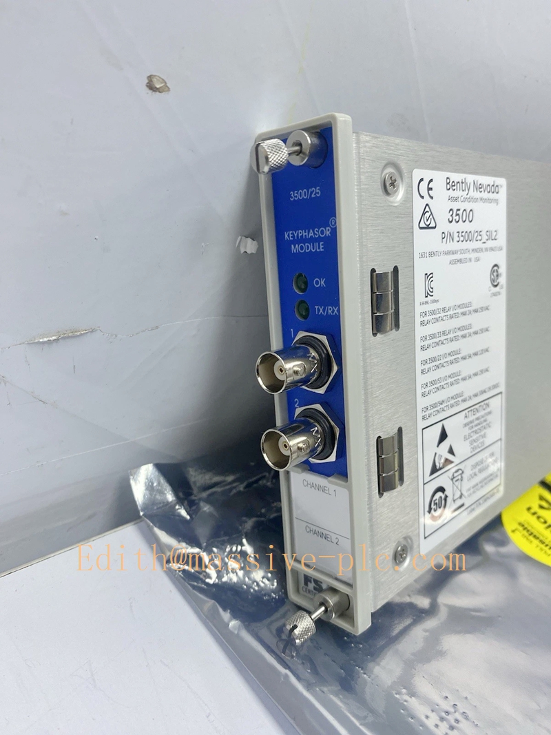
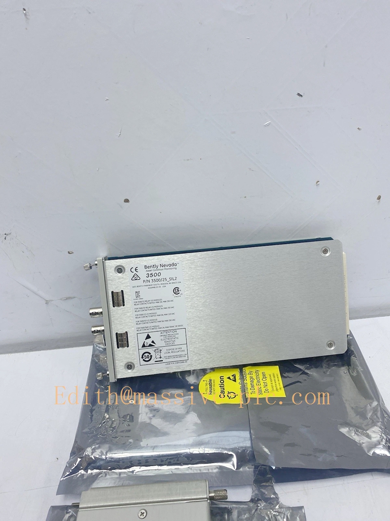
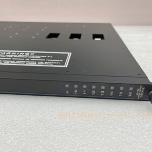
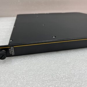
Bently‑Nevada 3500/25‑02‑01‑00 Enhanced Keyphasor Assembly (149369‑01 Main Board +125800‑01 Rear I/O Module)
Product Description
The 3500/25‑02‑01‑00 is a half‑height enhanced Keyphasor timing reference assembly for Bently‑Nevada 3500‑M‑series machinery‑protection rackBaker Hugh…. It is assembled with front logic main board 149369‑01 and rear I/O daughter‑board 125800‑01 (internal termination type).
This module accepts raw pulse input from proximity probe or magnetic pickup transducer installed on rotating shaft, converts analog trigger signal into precise digital once‑per‑turn Keyphasor timing pulses, and distributes reference signal to all monitor modules across the rack via backplane bus. It provides critical phase‑angle reference for shaft speed calculation, 1X vibration amplitude & phase measurement, orbit plotting, startup/coast‑down transient analysis and overspeed protection logic.
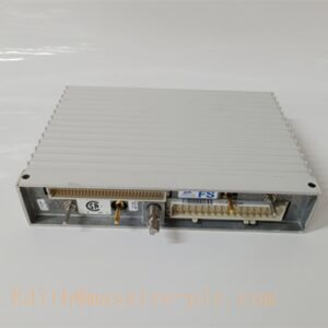
The 125800‑01 rear module adopts internal screw‑terminal termination for field sensor wiring. This assembly cannot work standalone; it relies on rack backplane power and TDI for configuration and event logging. OEM manufacturing discontinued; supplied only as aftermarket replacement spare for legacy turbomachinery TSI systemses.Made-in….
Order code breakdown:3500/25‑02‑01‑00-02:Rear I/O = internal‑termination Keyphasor I/O (125800‑01)-01:Standard signal processing variant-00:No third‑party safety agency certification
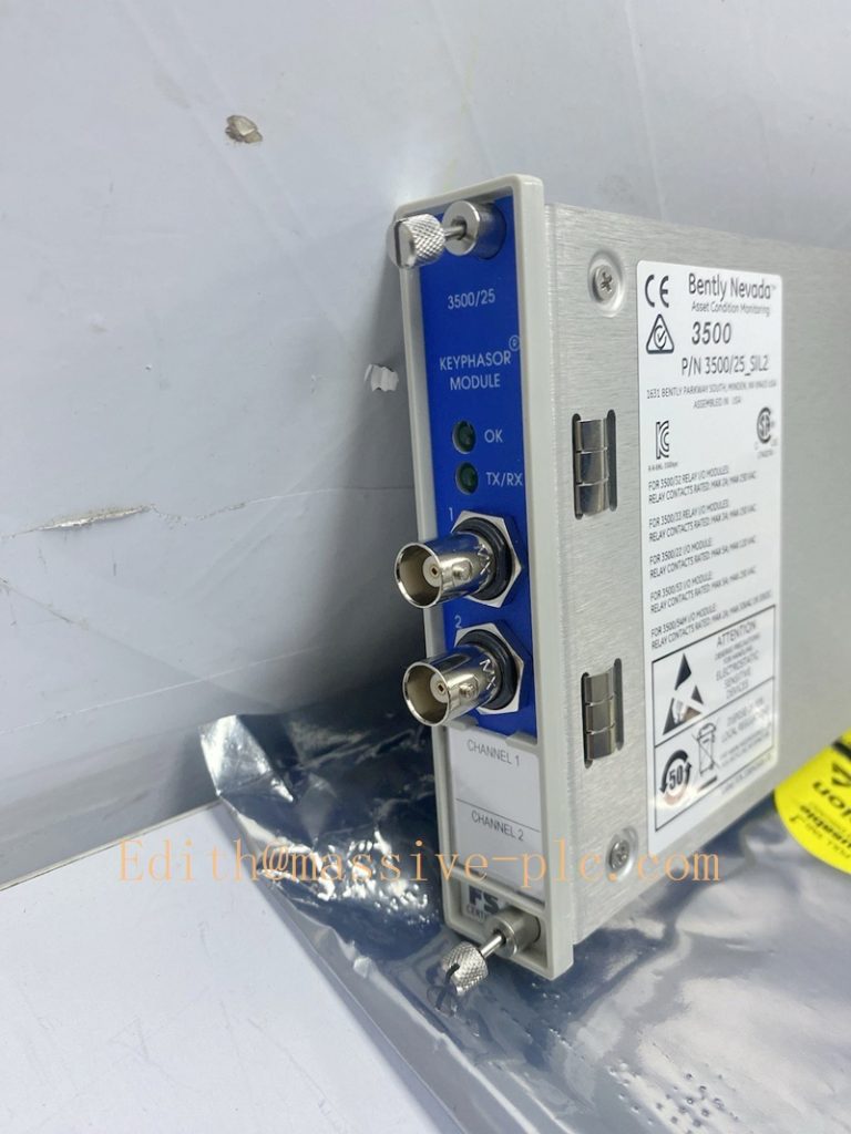
149369-01
Technical Specifications
| Item | Specification |
|---|---|
| Complete Assembly PN | 3500/25‑02‑01‑00 |
| Front Main Processor Board | 149369‑01 (Enhanced Keyphasor CPU board, 2‑channel) |
| Rear I/O Daughter‑Board | 125800‑01 (Keyphasor I/O, internal screw‑terminal termination, non‑isolated) |
| Form Factor | Half‑height module |
| Channel Quantity | 2 independent Keyphasor input channels |
| Supported Transducer | Proximity probe, magnetic pickup sensor |
| Input Signal Type | Analog pulse signal from shaft keyway / gear tooth |
| Max Shaft Speed Measurement | 200,000 RPM |
| Output to Backplane | Digital Keyphasor timing pulse for rack monitor modules |
| Front‑panel Indicator | OK LED, per‑channel status LED for signal detection & fault alarm |
| Typical Power Consumption | 3.8 W |
| Supported Rack Quantity | Max 4 Keyphasor channels in single rack (2pcs 3500/25 module); up to 8 channels under paired configurationBaker Hugh… |
| Operating Temperature | ‑30 °C ~ +65 °C (‑22 °F ~ +149 °F) |
| Storage Temperature | ‑40 °C ~ +85 °C (‑40 °F ~ +185 °F) |
| Relative Humidity | 5‑95 % RH, non‑condensing |
| Dimension(H×W×D) | 241 mm ×12.2 mm ×242 mm (9.50 in ×0.48 in ×9.52 in) |
| Approximate Total Weight | 0.38 kg (0.84 lbs) |
| Product Status | Discontinued OEM production, aftermarket spare‑part only |
Variant note:-125800‑02:Isolated internal‑termination rear I/O, optimized for magnetic pickup application-126648‑01:External‑termination rear I/O version
Key Features & Benefits
- Precise shaft timing reference: Converts shaft key‑mark trigger into high‑accuracy digital timing pulse, which is fundamental for phase‑related diagnostic calculation including 1X vector, orbit, bode & polar plot for System 1 software analysises.Made-in….
- Dual‑channel half‑height compact design: Two independent input channels within half‑height slot, optimizes rack slot utilization; multiple modules can be installed for multi‑shaft or redundant Keyphasor requirement; supports TMR system redundant timing input by dual‑module parallel deploymentBaker Hugh….
- Internal field termination: Field sensor cable directly connects to screw terminals on rear‑side 125800‑01 module, eliminating extra external terminal blocks and reducing cabinet wiring complexity.
- Comprehensive channel self‑diagnosis: Detects transducer open‑circuit, short‑circuit, signal loss and abnormal trigger events; fault events will be logged to rack event‑log and indicated by front‑panel LED.
- Full backward‑compatibility: 149369‑01 main board is drop‑in replacement for older 125792‑01 main‑board; compatible with all 3500‑M‑series monitors, TDI and legacy firmwareBaker Hugh…. Rear‑side 125800‑01 I/O supports hot‑swap under rack powered‑on; front main‑board requires slot power‑down before removal.
- Supports overspeed protection function: Delivers speed‑reference signal for 3500/50 speed monitor module to implement turbine/compressor overspeed protection interlock.
Application Fields
- Power‑generation, petrochemical and oil‑gas facilities: Provides Keyphasor timing reference signal for steam turbine, gas turbine, centrifugal & axial compressor 3500‑M TSI racks; cooperates with vibration, displacement and speed monitor modules for rotating‑machinery protection and condition‑diagnosis.
- Machinery monitoring projects requiring shaft speed measurement, phase‑angle analysis, orbit and startup‑coast‑down transient data capture.
- Spare‑part replacement and retrofit for legacy 3500‑M racks originally equipped with internal‑termination variant 3500/25‑02‑01‑00 Keyphasor assembly.
Related Recommended Products
- 3500/22‑01‑01‑00 (TDI): Rack gateway for configuration download and event‑log reading
- 3500/15 series: Rack power‑supply modules
- 3500/40M / 3500/42M / 3500/50: Monitor modules consuming Keyphasor timing reference signal
- 125800‑02: Isolated rear I/O alternative for magnetic‑pickup heavy‑noise field environment
- 3500 Rack Configuration Software: Tool for Keyphasor channel parameter setup
Installation and Maintenance
Installation
- Mate front main‑board 149369‑01 firmly with rear‑side 125800‑01 I/O module; insert half‑height assembly into any available half‑height slot of 3500 rack.
- Wire proximity probe or magnetic‑pickup field cables directly onto screw terminals of 125800‑01 rear module, strictly follow sensor wiring specification.
- Launch 3500 Rack Configuration Software, enable corresponding Keyphasor channel, configure trigger threshold, expected tooth count and speed‑monitor associated parameters, download configuration to rack.
- Power‑up rack; verify front‑panel OK‑LED is illuminated; check rack event‑log for channel fault diagnostics. Rotate shaft manually to confirm valid Keyphasor trigger detection.
Important Note: Only rear‑side 125800‑01 supports hot‑swap. Front‑side 149369‑01 main‑board must be installed or removed with corresponding slot power disabled. This module only provides timing reference signal and does not perform protection voting logic itself.
Maintenance
- Periodically inspect rear‑module screw terminals and connectors for dust accumulation, corrosion and loose wiring connections.
- Regularly review rack event‑log for Keyphasor channel fault, signal‑loss and transducer failure alarms.
- For rear‑I/O circuit fault: hot‑swap 125800‑01 while rack remains powered‑on, verify channel trigger detection function after replacement.
- For main‑board logic fault: power‑down assigned half‑height slot before extracting 149369‑01 main‑board; reassemble with matched rear I/O module, download rack configuration and validate full‑function recovery.
- Avoid mechanical shock and conductive contamination during module handling. Refer to Bently‑Nevada official document Doc‑141532 (3500/25 Enhanced Keyphasor Datasheet) for full installation constraints and detailed troubleshooting guidanceBaker Hugh…

 Start Chat




