
Description
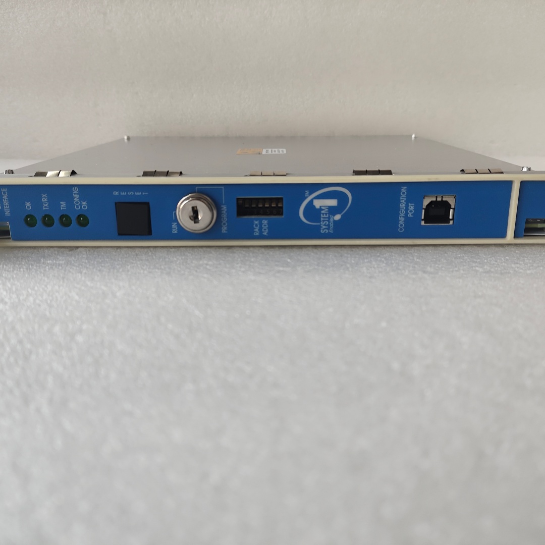
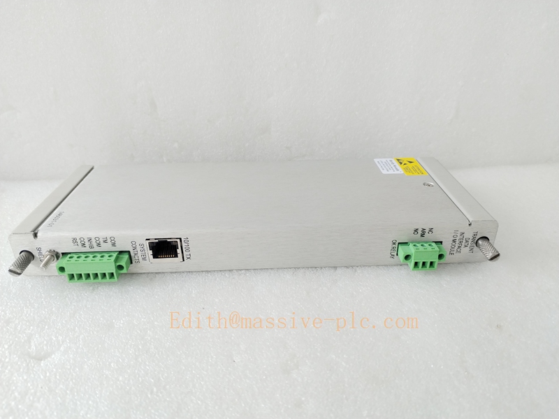
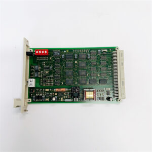
Bently‑Nevada 3500/22‑01‑01‑00 Transient Data Interface Assembly (288055‑01 Main Board + 146031‑01 Rear I/O Module)
Product Description
The 3500/22‑01‑01‑00 (TDI‑Transient Data Interface) is the mandatory rack‑level gateway for Bently‑Nevada 3500‑M‑series machinery protection rack本特利. The complete assembly consists of front‑side main processor board 288055‑01 and rear‑mount copper Ethernet daughter‑board 146031‑01 (10Base‑T /100Base‑TX).
It merges the traditional rack management function of legacy 3500/20 RIM and high‑speed transient data acquisition capability formerly performed by TDX‑net communication processor. Installed in fixed Slot 1 next to rack power supply, it communicates with all monitor modules over rack backplane bus, collects steady‑state measurements, alarm status, orbit, spectrum and startup/coast‑down transient data, and transmits data to System 1® machinery diagnostic software via Ethernet portBaker Hugh…. Front‑panel USB‑B port supports local laptop commissioning by 3500 Rack Configuration Software.
TDI only handles communication and rack administration; it does not participate in machinery protection voting logic. Communication faults will not affect hard‑wired alarm and trip outputs of monitor & relay modules. OEM production discontinued; supplied as aftermarket replacement spare for legacy turbomachinery TSI systems本特利.
Technical Specifications
| Item | Specification |
|---|---|
| Complete Assembly PN | 3500/22‑01‑01‑00 |
| Front Main Processor Board | 288055‑01 (TDI CPU board, with front‑panel USB‑B port & OK relay) |
| Rear Ethernet I/O Daughter‑Board | 146031‑01 (10/100 Base‑TX copper RJ45 Ethernet, auto‑negotiation)Baker Hugh… |
| Rack Installation Slot | Fixed Slot 1 (adjacent to power supply module) |
| Front‑panel Interface | USB‑B for local configuration; OK status SPDT relay output |
| Network Interface | Rear RJ45: 10 / 100 Mbps IEEE802.3u twisted‑pair Ethernet |
| Supported Software | System 1® Condition‑Monitoring Software, 3500 Rack Configuration Software |
| Dynamic Data Capacity | Orbit plot, vector, full spectrum, start‑up / coast‑down transient capture; max frequency span 30 kHz |
| OK Relay Contact Rating | 5 A @24 VDC /120 VAC; gold‑plated low‑level contacts 1 mA @1 V minimum |
| Typical Power Consumption | 10.5 W |
| Form Factor | Full‑height front main board + full‑height rear plug‑in I/O daughter‑board |
| Operating Temperature | ‑30 °C ~ +65 °C (‑22 °F ~ +149 °F) |
| Storage Temperature | ‑40 °C ~ +85 °C (‑40 °F ~ +185 °F) |
| Relative Humidity | 5‑95 % RH, non‑condensing |
| Dimension(H×W×D) | 241 mm × 24.4 mm × 242 mm (9.50 in × 0.96 in × 9.52 in) |
| Approximate Total Weight | 0.72 kg (1.59 lbs) |
| Product Status | Discontinued OEM production, aftermarket spare‑part only |
Ordering code breakdown:
- 01:Standard TDI main board
- 01:10/100 Base‑TX copper Ethernet rear I/O (146031‑01)
- 00:No third‑party agency certification
Key Features & Benefits
- Integrated rack management + high‑speed transient acquisition: Replaces separate RIM and TDX‑net hardware. Performs rack health supervision, configuration access and dynamic fault‑waveform collection in one single full‑height module.
- Rich dynamic diagnostic dataset: Captures orbit, vector, spectrum and transient startup‑coast‑down data; configurable trigger conditions based on speed band, delta‑RPM or time stamp; built‑in pre‑trigger buffer preserves fault history for post‑event analysis.
- Dual access interfaces: Rear‑side 10/100M copper Ethernet for continuous data upload to System 1 host; front‑panel USB‑B enables local on‑site commissioning without plant network connection.
- System health dry‑contact relay: OK‑relay provides remote rack‑health status signal to DCS/SCADA system for overall rack supervision.
- Safety decoupled from protection chain: All protection voting, alarm and trip functions run independently within monitor modules. TDI communication failure cannot disable machinery protection functions本特利.
- Backward‑compatible maintainable architecture: Compatible with all 3500‑M‑series monitors, power supplies and legacy firmware. Rear‑side 146031‑01 I/O supports hot‑swap under powered‑on condition; front‑side 288055‑01 CPU board requires slot power‑down before removal.
Application Fields
- Power‑generation, petrochemical and oil‑gas facilities: serves as central rack gateway for steam turbine, gas turbine, centrifugal / axial compressor 3500‑M TSI racks, delivering vibration, displacement, speed transient data to System 1 predictive diagnostic platform.
- Turbomachinery condition‑monitoring projects requiring both rack configuration management and high‑speed dynamic waveform recording.
- Spare‑part replacement and retrofit for existing 3500‑M racks originally equipped with copper‑Ethernet variant 3500/22‑01‑01‑00 TDI assembly.
Related Recommended Products
- 3500/15 series: Rack power‑supply modules
- 3500‑M monitor family: 3500/40M, 3500/42M, 3500/50, 3500/60 etc., data source for TDI transient acquisition
- 146032‑01: Alternative rear I/O (100Base‑FX fiber‑optic Ethernet) for heavy‑EMI long‑distance network environmentBaker Hugh…
- System 1® Condition‑Monitoring Software: Host diagnostic workstation
- 3500 Rack Configuration Software: Parameter setup, configuration download and event‑log reading tool
Installation and Maintenance
Installation
- Mate 288055‑01 front main board firmly with 146031‑01 rear Ethernet I/O module; insert complete assembly into fixed Slot 1, the first slot adjacent to rack power supply.
- Wire OK‑relay dry‑contact terminals to external DCS/SCADA status‑input circuit following project safety schematics.
- Connect RJ45 twisted‑pair Ethernet cable to rear‑side 146031‑01 port for System 1 host link; connect USB‑B cable to front‑panel port for local configuration laptop when needed.
- Launch 3500 Rack Configuration Software, set transient‑data parameters including frequency span, trigger source and orbit‑channel pairing, download configuration to rack.
- Power‑up rack; confirm front‑panel OK‑LED is lit; inspect rack event‑log for TDI self‑diagnosis, backplane‑communication and Ethernet‑link status alarms.
Important Note: Must occupy Slot 1. Only rear‑side 146031‑01 supports hot‑swap. Front‑side CPU board 288055‑01 must be installed or removed with corresponding slot power disabled. TDI does not execute machinery‑protection voting.
Maintenance
- Periodically inspect rear Ethernet port, OK‑relay terminals and front‑panel USB‑B connector for dust and loose connections.
- Regularly check rack event‑log for TDI fault, backplane communication error or Ethernet link‑down alarms; troubleshoot plant network infrastructure for communication dropout issues.
- Communication fault on rear I/O: hot‑swap 146031‑01 while rack remains powered‑on, verify Ethernet link and transient‑data uploading after replacement.
- Main‑board failure: power‑down Slot 1 before extracting 288055‑01 CPU board; reassemble with matched rear I/O module, download rack configuration and validate full‑function recovery.
- Avoid mechanical shock and conductive contamination during module handling. Refer to Bently‑Nevada official document Doc‑161581 (3500/22M TDI Datasheet & Manual) for full installation constraints and detailed troubleshooting guidanceBaker Hugh…


 Start Chat




