
Description
Bently Nevada 3500/20 (125744-02) Rack Interface Module Product Introduction
Product Overview
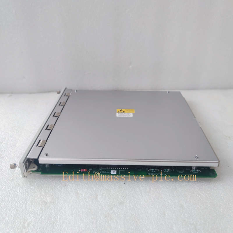
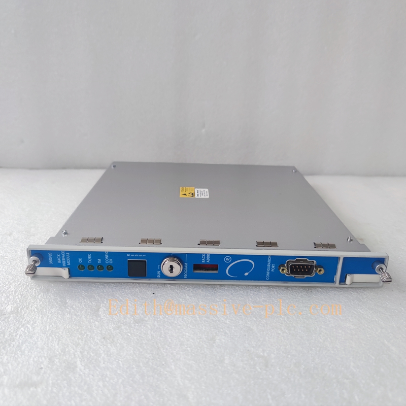
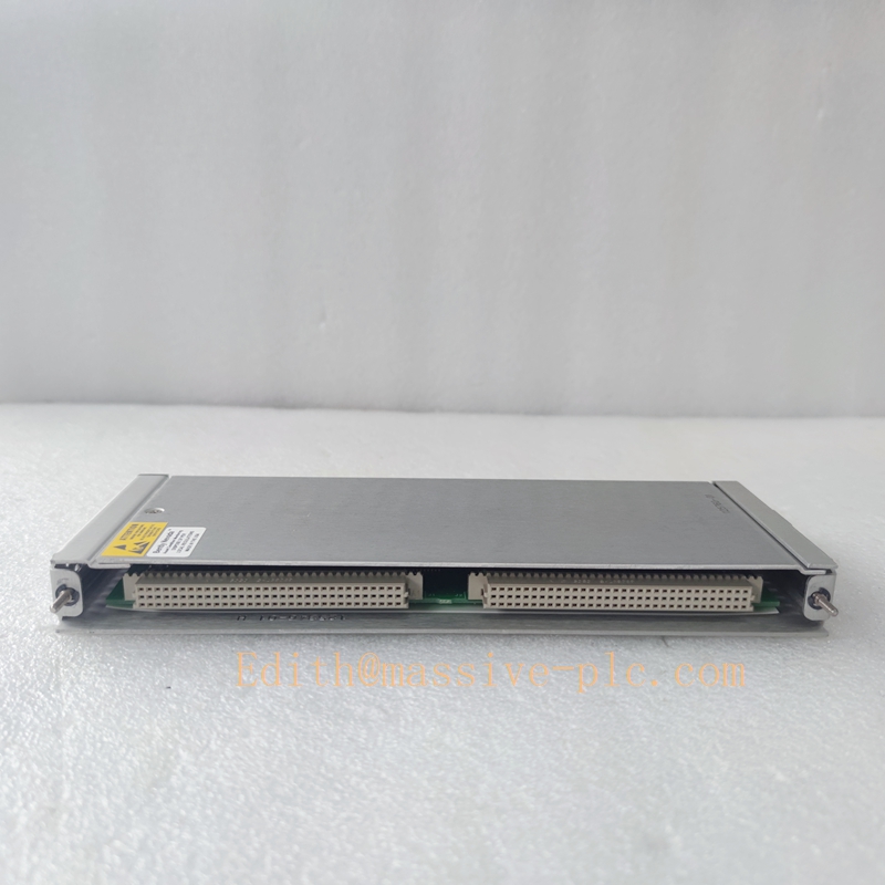
The Bently Nevada3500/20 (Part No. 125744-02) is a core Rack Interface Module designed exclusively for the Bently Nevada 3500 series machinery condition monitoring system. Serving as the central communication and management gateway of the entire 3500 monitoring rack, it undertakes rack-level data convergence, host computer communication, system configuration management, and rack status monitoring. As a mandatory base module for every complete 3500 monitoring rack, it bridges all internal monitoring I/O modules and external upper monitoring systems, realizing unified data transmission, parameter configuration and fault diagnosis of the whole rack.
The 125744-02 is the mainstream upgraded hardware revision of the 3500/20 module, featuring stronger anti-interference performance, more stable bus communication and wider industrial environmental adaptability. It supports system hot configuration, real-time data uploading, rack health self-diagnosis and redundant communication expansion. Widely used in rotating machinery safety monitoring scenarios in high-risk industrial industries, it ensures continuous, accurate and reliable transmission of vibration, displacement, temperature and rotational speed monitoring data, and is the core guarantee for stable operation of Bently Nevada 3500 industrial monitoring systems.
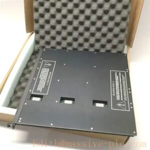
Bently Nevada 3500/20 125744-02
Series Model Classification & Peer Models
The 3500/20 belongs to the Bently Nevada 3500 Series Machinery Monitoring System Core Modules, positioned as the rack-level unified interface and management unit. It has clear series iteration rules and matching peer modules, forming a complete industrial monitoring hardware system:
2.1 Model Iteration Description: 125744-02 is the latest stable hardware revision of 3500/20, optimized for circuit anti-aging, EMC electromagnetic compatibility and long-term operational stability, fully replacing early 125744-01 versions.
2.2 Same-Series Core Peer Modules
3500/15: System power supply module, providing stable redundant power supply for the entire rack, cooperating with 3500/20 to complete rack system operation.
3500/22: Enhanced transient data interface module, used for high-speed dynamic data acquisition and waveform recording, expanding the advanced monitoring function of 3500/20.
3500/40: Proximity/Displacement monitoring module, responsible for shaft vibration and shaft displacement signal acquisition, matching 3500/20 for data upload.
3500/42: Velocity vibration monitoring module, used for casing vibration signal collection, realizing full-station machinery monitoring with 3500/20.
2.3 System Compatibility: Fully compatible with all Bently Nevada 3500 series rack chassis, I/O monitoring modules and configuration software, supporting full-system hardware matching and seamless software debugging.
Core Technical Specifications & Product Specifications
| Parameter Item | Technical Specifications |
| Product Model | 3500/20 Rack Interface Module |
| Hardware Part Number | 125744-02 |
| Module Positioning | Full rack data gateway & system management core module |
| Communication Interface | RS232/RS485 serial port, dedicated 3500 system bus interface |
| Communication Protocol | Bently dedicated monitoring protocol, supporting upper computer configuration software docking |
| Data Processing Capacity | Supports full rack multi-channel monitoring data convergence and real-time upload |
| Configuration Function | Online hot configuration, parameter modification, program downloading and debugging |
| Diagnostic Function | Full rack module status monitoring, bus fault diagnosis, power abnormality alarm |
| Working Voltage | +5VDC / +24VDC standard industrial rack power supply |
| Operating Temperature | -20℃ ~ +65℃ industrial standard temperature range |
| Working Humidity | 5%~95% RH, non-condensing |
| Industrial Grade | Enhanced EMC anti-interference design, suitable for harsh industrial vibration environments |
| Installation Method | Standard 3500 rack plug-in installation, fixed locking design |
Core Product Features
4.1 Full-Rack Unified Data Gateway Capability
The 3500/20 (125744-02) serves as the only data export gateway of the 3500 monitoring rack. It uniformly converges vibration, displacement, temperature, speed and other monitoring data of all I/O modules in the rack, realizes centralized data sorting, verification and transmission, and solves the problems of scattered data and difficult unified management of traditional monitoring racks. It ensures the consistency and integrity of full-station machinery monitoring data.
4.2 Stable & Anti-Interference Industrial Communication Performance
The upgraded 125744-02 hardware version optimizes the internal circuit and signal shielding structure, with stronger EMC electromagnetic compatibility and anti-vibration capability. It can resist strong electromagnetic interference and mechanical vibration in industrial sites, ensuring zero packet loss and zero distortion of monitoring data during long-distance and long-term transmission. It adapts to harsh working conditions such as thermal power, petrochemical and metallurgy.
4.3 Online Hot Configuration & Dynamic Debugging
The module supports online hot configuration function. Users can modify monitoring parameters, adjust alarm thresholds, configure channel attributes and upgrade programs through upper computer software without shutting down the rack or stopping equipment monitoring. It realizes zero monitoring blind spot system debugging and parameter optimization, greatly improving the flexibility and efficiency of industrial equipment monitoring management.
4.4 Full-System Intelligent Self-Diagnosis & Alarm
It integrates multi-dimensional full-rack self-diagnosis mechanism, which can real-timely monitor the operating status of all modules in the rack, bus communication status, power supply status and internal operation abnormalities of the interface module itself. It automatically generates fault codes and alarm prompts, accurately locates faulty modules and fault types, helps operation and maintenance personnel quickly eliminate hidden dangers, and improves the overall reliability of the monitoring system.
4.5 High Compatibility & Strong System Scalability
The 3500/20 (125744-02) has full compatibility with all 3500 series rack devices and monitoring modules, supporting flexible expansion of monitoring channels and functional modules. It can seamlessly dock with various industrial upper monitoring platforms and DCS systems, realizing remote data viewing, centralized alarm management and equipment operating condition analysis, with strong system integration and scalability.
4.6 Long-Term Operational Stability & Low Failure Rate
Adopting industrial-grade anti-aging components and optimized circuit design, the module has excellent long-term operational stability, resisting environmental erosion such as high temperature, humidity and industrial dust. It supports 24/7 uninterrupted operation of the monitoring system for a long time, with extremely low failure rate, reducing system downtime and maintenance frequency.
350020 125760-01
Main Core Functions
5.1 Full-Rack Monitoring Data Convergence & Upload
Uniformly collects and converges real-time monitoring data of all vibration, displacement, temperature and speed I/O modules in the 3500 rack, sorts and verifies the data, and stably uploads it to the upper configuration software and industrial monitoring platform. It provides complete and accurate original data support for equipment condition analysis and fault early warning.
5.2 System Configuration Management & Program Execution
Undertakes the core configuration management function of the entire monitoring rack, receives and executes user configuration instructions such as channel enabling, alarm threshold setting and monitoring mode adjustment. It uniformly manages the operating logic and parameter status of all modules in the rack, ensuring standardized and unified operation of the whole system.
5.3 Rack System Status Monitoring & Fault Alarm
Real-timely monitors the operating status of the rack power supply, internal bus, each I/O module and its own hardware circuit. It automatically triggers alarm prompts for abnormal power supply, communication failure, module offline and parameter abnormality, and records detailed fault logs to facilitate subsequent fault tracing and analysis.
5.4 Upper & Lower Computer Communication Docking
As the bridge between the lower monitoring hardware and the upper industrial control system, it realizes two-way data interaction between the 3500 monitoring rack and external DCS, SCADA and monitoring host. It supports real-time data viewing, remote parameter modification and system online debugging, realizing intelligent remote management of industrial equipment.
5.5 System Synchronization & Data Calibration
Undertakes full-rack system time synchronization and data synchronous sampling management, ensures consistent sampling time and unified data benchmark of each monitoring channel, eliminates data deviation caused by asynchronous operation of modules, and improves the accuracy and comparability of equipment monitoring data.
Industrial Application Scenarios
The Bently Nevada 3500/20 (125744-02) rack interface module is widely used in full-industry rotating machinery condition monitoring and safety protection scenarios, covering thermal power generation, petrochemical, natural gas transmission, coal chemical, metallurgy, cement and other heavy industrial fields. It is the core management and communication module of the Bently Nevada 3500 professional machinery monitoring system.
Typical application equipment includes: steam turbines, gas turbines, centrifugal compressors, blowers, pumps, fans and other key large-scale rotating equipment. It is responsible for centralized management and data transmission of equipment vibration, shaft displacement, bearing temperature and overspeed monitoring systems, realizing real-time condition monitoring, fault early warning and abnormal alarm protection of key industrial equipment, avoiding equipment failure and shutdown accidents, and ensuring safe, stable and efficient operation of industrial production equipment.
Standard Installation Guidelines
7.1 Pre-Installation Preparation
Before installation, verify that the module model (3500/20 125744-02) matches the system configuration, check the module circuit board for damage, pin oxidation and accessory integrity. Confirm the rack power supply is cut off, the installation environment is dust-free, dry and vibration-isolated, and prepare professional anti-static tools and standard communication cables to avoid static damage to precision circuits.
7.2 Rack Installation Steps
The module adopts standard 3500 rack card slot plug-in installation. Align the module with the dedicated guide rail of the rack interface slot, push it smoothly and horizontally into the card slot until it is closely attached to the backplane bus, and tighten the fixing screws on both sides of the module to prevent poor contact caused by equipment vibration. Ensure the module is fully inserted and the bus connection is reliable without virtual connection or offset.
7.3 Communication Wiring Specification
Adopt shielded dedicated communication cables for upper computer wiring, standardize RS232/RS485 interface wiring, avoid mixed wiring with power cables to prevent electromagnetic interference. The wiring terminals must be firm and reliable with no loose wiring or bare wire exposure. Complete wiring in strict accordance with the system schematic diagram, and conduct communication continuity test after wiring is completed.
7.4 Post-Installation Debugging
After installation and wiring, power on the rack slowly, observe the module indicator status, connect the upper configuration software for online debugging. Verify normal rack communication, full-module status identification and normal data upload function, complete system time synchronization and parameter calibration, and confirm that the self-diagnosis and alarm functions are effective.
Daily Maintenance & Fault Maintenance Guidelines
8.1 Daily Routine Maintenance
Regularly check the module operating status, indicator lights and rack operating temperature and humidity to ensure operation within the standard environmental range. Regularly clean the module surface and rack internal dust to avoid dust accumulation affecting heat dissipation and bus contact. Regularly check communication wiring firmness and shielding grounding status to prevent signal interference and communication interruption. Regularly back up system configuration parameters and fault logs to ensure data traceability.
8.2 Common Fault Diagnosis & Maintenance
Communication Abnormality: When the upper computer cannot connect or data is lost, first check the communication cable wiring and interface looseness, verify the consistency of communication protocol and baud rate, clean the module interface pins, and eliminate line and configuration faults.
Rack Module Offline Alarm: Check the module insertion status and backplane bus contact, eliminate poor contact caused by vibration or dust accumulation, restart and reset the module after confirming no hardware damage.
System Configuration Failure: Check whether the module program version matches the system, eliminate program bugs and configuration parameter conflicts, and re-download and calibrate the system program.
8.3 Module Replacement & Upgrade Maintenance
For faulty modules that cannot be repaired, power off the rack safely, remove the fixing screws to pull out the faulty module, insert the new 125744-02 module in place and fix it firmly. After replacement, perform system communication debugging, parameter restoration and data calibration to ensure the whole rack system runs normally. Regularly upgrade the module firmware to optimize system stability and anti-interference performance.
8.4 Spare Module Storage & Aging Maintenance
Spare 3500/20 modules need to be stored in a constant-temperature, dry and dust-free anti-static environment to avoid moisture, static electricity and mechanical collision. For long-term operating modules, regularly check circuit aging, interface oxidation and bus transmission stability, and replace aging modules in advance to prevent sudden system failure.
| 3500/05-01-01-00-00-01 |
| 3500/15-02-02-00 (106M1079-01+106M1081-01) |
| 3500/22-01-01-00 (288055-01+146031-01) |
| 3500/05-01-02-00-00-00 |
| 3500/15(106M1079-01+106M1081-01) |
| 3500/22M (138607-01+146031-01) |
| 3500/42M (176449-02+128229-01) |
| 3500/25-02-01-00(149369-01+125800-01) |
| 3500/25-01-01-00 (149369-01+125800-01) |
| 3500/60-01-00 (163179-01+133819-01) |
| 3500/33-01-00(149986-01+149992-01) |
| 3500-92(136188-02+136180-01) |
| 3500/65-01-00 (145988-02+172103-01) |
| 3500/04-01 138257-01 |
| 3500/70M-03-00(176449-09+135489-01) |
| 3500/70M-05-00(176449-09+135489-03) |
| 3500/72M-03-00(176449-08+140471-01) |
| 3500/92-01-01-00(136180-01+125736-01) |
| 3500/42-06-00 (176449-02+135489-03) |
| 3500/42-09-00 (176449-02+140471-01) |
| 3500/22-01-01-00 (288055-01+146031-01) |
| 3500/25-01-03-00 (149369-01+125800-01) |
| 3500/32-01-00 (149986-02+125720-01) |
| 3500/33-01-00 (149986-01+149992-01) |
| 3500/60-05-00 (163179-01+136711-01) |
| 3500/92-02-01-00 (136180-01+133323-01) |
| 3500/92-04-01-00 (136180-01+136188-02) |
| 3500/05-01-01-00-00-01 |


 Start Chat




